Droid Builder
Extra Projects & Event Page's
- Home
- Trading Card Dispenser (version 2) - TCD [2020/2022]
- Trading Cards
- R5-D4's ....Bad Motivator development
- R5-D4 - silver neck details
- R4-D4 - Dome [wood build]
- R0-D4 Dome [wood build]
- 3D Printing - Star Wars stuff
- *** Star Wars Shoes ***
- Event: Droids @Mshed Bristol 2026
- Event: Droids @Mshed Bristol 2025
- Event: Droids @Mshed Bristol 2024
- Event's 2018
- Event's 2017
- Event 2016 - "Celebration Europe"
- Event's 2015
- Event 2014 - Chippenham Sci-Fi
- R5-D4 - events page - The beginning (2013)
- ** R5-D4 patch **
- R5-D4 Photos
- Costume for my Son - Han Solo -
- Costume for my Son - Boba Fett
- Droid Caller - Han Solo style
- Scanning Crew Container - Transmitter Storage Box
- Stormtrooper - me
- Rogue One - trading card storage box
- Rogue One
- Jabba’s gate prop for Celebration 2023
- GOUD-4 Messenger Droid - Solo ASWS
- Treadwell Droid - WED-15-77
November 17, 2025
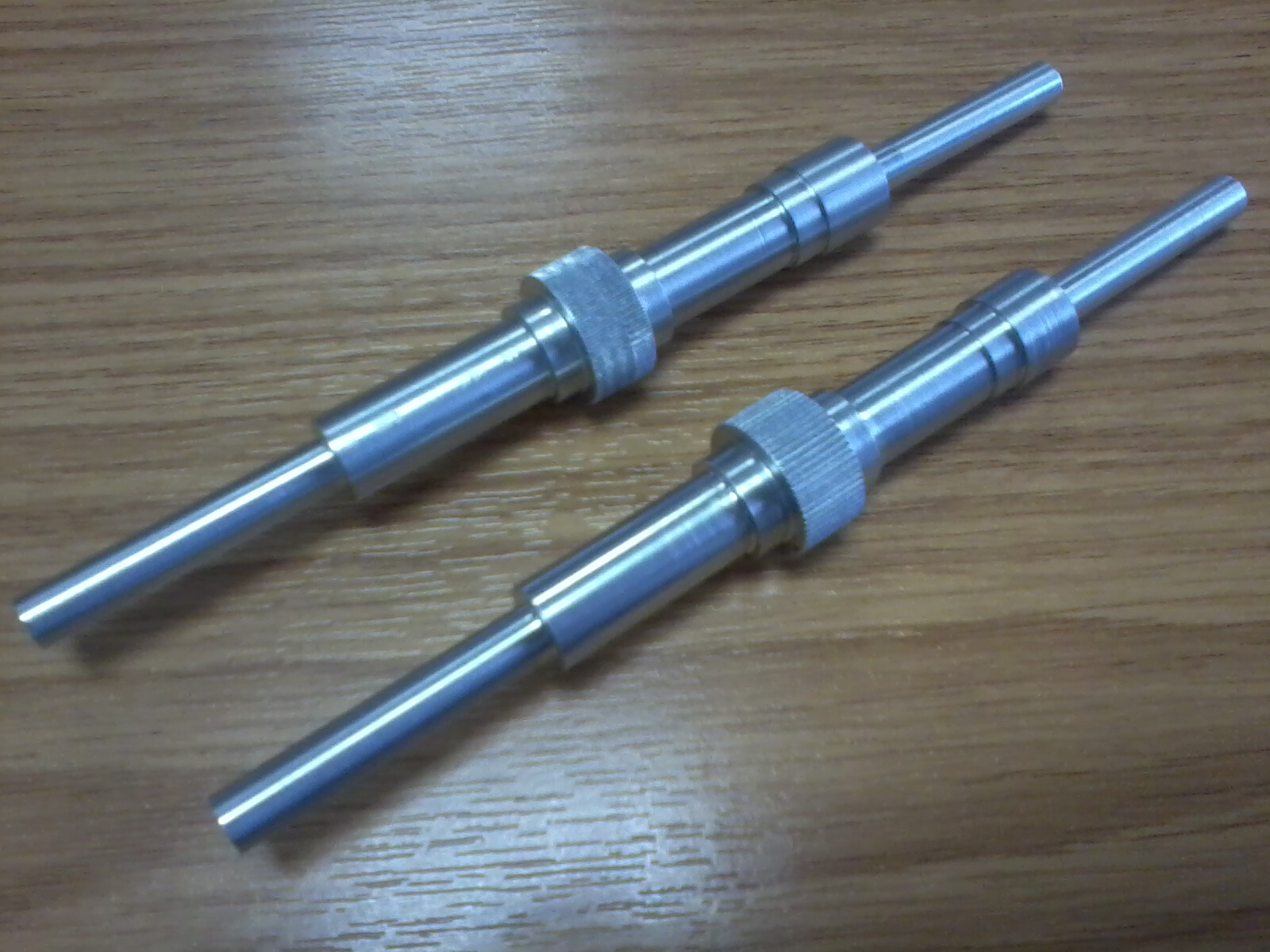
Machining parts for Mike B
June 25, 2024
R5-D4 dome build - on this day 2013
June 07, 2024
Shoulder hubs - Aluminium - Paul’s R2 No2
Above picture, show how much material had to be removed. Using a manual milling machine, means you having to do everything by hand lol.
April 05, 2023
Treadwell WED-15 droid build : Part 14
I dug around in my servo box and remembered that I had this nano servo I bought back in 2020 for the ‘life form scanner’ project idea.
April 03, 2023
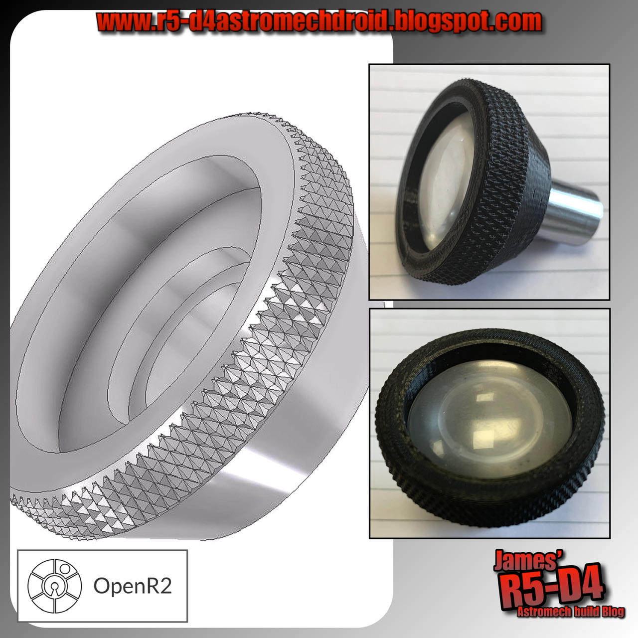
Screen accurate R5 eyes - found part by OpenR2
Items also
(possibly) used that match is the vinyl sweep brush which resembles R5’s
antenna.
I have always found the search for these found items to be of great interest, so this was something that I had to follow up on. Online searches revealed the record deck's history and more [see Transcriptor link above].
So using the 3D CAD model I had already drawn up years ago, I started on modifying a version to match that of the image supplied by OpenR2.I also had to find out how to draw up a knurled effect. Previous jobs have only required the superimposed image of a knurl, but I needed the actual knurl for 3D printing. I found a quick tutorial on YouTube which helped put me in the right direction as to which creative option to use, 'coil'. Once one groove was created, I then copied in 'circular' to multiply around the diameter. Next was to create a new 'work plane', and offset it half the distance of the knurled with. I then mirrored the original 'circular' grouping and this created the opposite grooves to create the knurled effect.
Eventually settled on version 'F'
Here’s the link: R5-D4’s Eyes - update
Back
to 2023 and here are the new more realistic eye pieces.
June 19, 2022
Reinventing the wheel……
Additional plates are on order, the two hashed areas on the 3D prints [above picture] are not needed so will be removed.
With the new frame layout, it will also be easier for me to access the ankle bolts, nut. On the original steel frame, I had the nut welded in place. Now, I’ve got nylock flanged nuts.
And here’s the completed assembly, with motor and caster fitted. This whole assembly is so much lighter than the old one.
June 11, 2022
Busy week: R5 motor bracket/3D designing and more….
January 20, 2021
R4-D4 dome - fitting Life-form scanner part 11
Installed the LFS into the dome. Two counter bored holes were drilled to allow the two countersunk head bolts to sit down inside the edge, allowing the lid to be closed flush. These have nylock nuts on the inside.
The aluminium tube thin walls are easily bent, ever so slightly from being man handled and installed..... think these may have to be replaced with either solid bar or steel, if I can find the size. Also remembering the first tube I bought had a thicker wall, but was a lot more cost wise. I would of liked to (of) kept the tube as LED wires could be run up inside.
Of course I had to do a manual test of everything. The lift worked, but not as smoothly as previously (slightly bent tube), but the principle still works. The lid panel was already opened lol :D I then powered up the servo tester to 'sweep' the LFS.
Next is to look at the Pololu controller and figure out the best way to activate everything. Am thinking I might not need the micro switches.......???
December 24, 2020
A Life-form scanner for R5-D4 - Part 8
Final 3D printed parts fitted and everything works as it should. Really pleased with how it runs.
Now it’s onto the electrical side of the project. The micro switches need diodes soldered across the contacts. This is so they return the flow of power but switch off the motor. The idea is that the power lift servo is a one button activation:- Press button, activates system.
- Motor lifts LFS, micro switch stops lift at top.
- Pololu control board activates scanner, set amount.
- Motor lowers LFS, micro switch stops lift at bottom.
This is the idea......have to see how it works out.
As promised, I’m putting a quick video together of this in action. I’ll post up the link to YouTube once complete.
December 23, 2020
A Life-form scanner for R5-D4 - Part 7
Fine tuning the design of the lower servo holder & the servo/tube connector.
The new normal sized servo's holes were NOT the same as my previous one, so needed to be slightly moved. I added the slot in the support for the support tube and also added splines for point contact only. Both of these will be getting re-printed again.
The pulley wheel got a new version printed, happy with how it turned out and that it works.....of course it works lol :D
Then this morning Royal Mail pulled their finger out and I received the micro switches, second aluminium tube AND.......
........the Pololu servo control board, from Hobbytronics!
So after the re-prints, it's onto the electronics, tho I will be looking/designing a holder for the board and the electronics. Thingiverse came up trumps again, case will be printed later. I'll also post up pictures of the full assembly.
December 20, 2020
A Life-form scanner for R5-D4 - Part 6
Design, 3D print, test fit.....& repeat lol.
All the bits fit so far, but I need to fit a second guide rail. I ordered another aluminium tube section to run parallel with the main one. This means more redesigning and printing of 3D parts, which I’ve already done.
For the scanner screen, I drilled some small holes in it and added white covered wire.
These will be glued in place later. Need to look at LED’s next.
A test of the pulley setup worked well, but the aluminium tube wall may cause problems as it is easily bent. This caused the guides to not run smoothly and the servo connection to the tube, broke. But this is all part of the design process.
May 01, 2011
Coin Slots - assembled
Friday I was out with the family at a local event to watch the Royal Wedding. But in the back on my mind was a nagging thought. Were the base dimensions correct???
So that evening, I had to reassure myself that I had drawn them up in the correct position, as everything get's built around these!!
PHEW!! They were. Also the arms I' marked up, also fitted (length). It's one thing to follow a set of plans, but following more than one with a few 'modifications' thrown in, makes things......... interesting lol :-D
April 28, 2011
Coin Slots - Machined Pt2
Managed to break one slot milling cutter :-D lol and I was only taking a small cut as well.
![]() |
| Machined Coin Slots |
I'm thinking about leaving the rads in the slots ??
I don't have a problem filing them out square, but thought it might me a nice touch, saying as the R5's were supposed to be a 'cheep' model.
Comments welcome please.
April 26, 2011
More Body work - Frame
Friday, I cut a strip of aluminium plate, to mount the coin slots onto.
Also cut lower support section for it. Just needs outside curve trimmed.
April 20, 2011
Coin Slots - Machined Pt1
Coin Slots
Cut two lower side supports for the side flat parts of the body.