Showing posts with label Speakers. Show all posts

July 07, 2025

R5’s Bad Motivator 2025

 February 2025.....

Back on it again these last few months, waiting for delivery of different components to get R5’s bad motivator setup all working from one switch off the RC transmitter.

A new receiver paired to use a different channel not used on main body, worked when bench testing, but didn't work when both receivers were powered up. So it's back to the drawing board on this.....

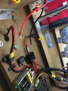
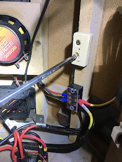
An Adafruit sound board, mini amplifier, voltage regulator and utilising a speaker out of my parts bin lol.

Then 3D printing of brackets to mount these parts.

Then one new momentary servo controlled switch to control the adafruit sound board, and one on/off switch for the ‘Bad Motivator smoke setup’.

April 14, 2023

Celebration Europe 2023 - Jabba's Gate Door Build - Part 4


February 2023:
More building work from Mike & he has excelled himself!!

He’d finished building the side unit and on Friday 17th, I went up to help him and his brother Mark, assemble the door.

There are three units that are bolted and screwed together to lock everything in place. When I arrived the base was already outside Mike’s place.

Next was bolting the support legs into place.

Then the upper support batons, that support the upper door unit. Mark & myself then lifted the upper section into place whilst Mike secured the batons to the rear.

We then carried out the lightest piece, the end wall. This gets bolted and screwed onto the other two units, making a rigid corner structure.

Mike brought out one of his droids and placed in front for scale and some more photos.

This was when the passing public started putting two and two together lol.

With the build almost completed, it’s just left for me to finish the TT-8Y droid. Mike has made the door flap panel to open up.

I have also made a start on writing up assembly instructions. This display will be handed over to the R2 Builders Club, for further events, so instructions for putting this together will be needed so anyone can do it.

TT-8Y droid progress:
The model components were designed to be static, but I required it to operate opening of the eye lid. So I had to do some thinking. One of the stl’s I didn’t print out as it wasn’t necessary and would of added to the weight. So I had to draw up some pivot point rings to allow the upper eye lid to be able to move.
Here you can see them on the lower fixed eye lid:
I had picked up some spray paint that I had used before and liked the colour of. With it i made a start on the pieces.

I wanted to check out the LED arrangement, so I first hot glued in the lens.

Then the LED holder plate. The LED’s were glued in.

The crystals were fitted in through the opening seen in above picture, one at a time lol.
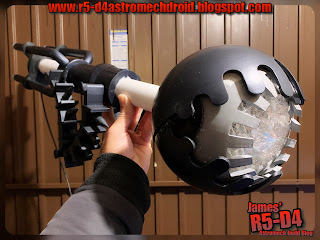
And here’s the finished crystal assembly:

Then it was a quick hook-up of the LED’s, not all of them are illuminated in the next pictures, it was just to see the effect.


So the next week or so will be more 3D printing of the arm extension.

I opened up part of the neck stl file and re-modelled it to have less material and also for it to be printed in two halves.
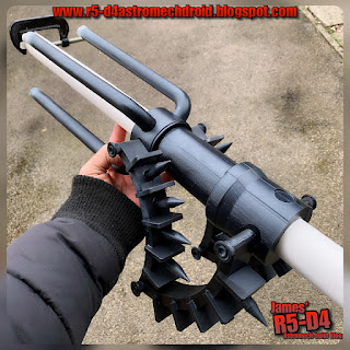
I had already printed off the ring that the four tubes fit onto. Next up was to remodel the tubes as the original ones were solid, no need for them to be, waste of material and additional unwanted weight. I used this same model and modified it to be straight, as an extra extension piece for the tubes. These were not actually needed in the end test fitting.

Once glued together and sanded. It was time to test assemble everything so far made.


I found some suitable length bolts and a steel length of rod. I drilled holes through the neck part and through the main PVC tube. Then the inner metal tube which will connect with the wall/door.

The next step was to disassemble it and start spraying up the pieces with the dark grey’ish paint, same colour as the eye lids. And here’s the reassembled parts. I still need to add the silver to these parts, as well as spraying the PVC tube.


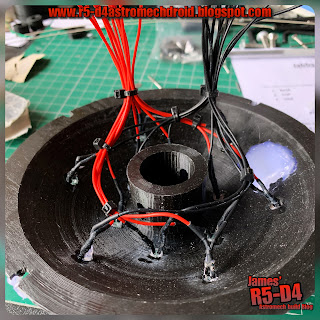
The LED wires were trimmed to matched lengths and soldered together. A single fly lead will connect to both positive and negative wires and terminated with a plug.

The connection plug was wired to a lead that is threaded through the PVC tube. So the eye can be removed from the main shaft.

Here’s a YouTube short. If this doesn't work, here's my YouTube Channel link


Some more pictures of the assembly.


I went through my speaker box and after a quick test, decided on one that was rectangular (out of an old laptop), this I will try to incorporate into the neck part of the build so the sounds will seam like they are coming from the eye itself. And here is the test install:
The PVC tube has a slot cut into it so that the speaker sits flush with the surface. I’ll be redoing this speaker holder.

I drew up an adapter that will be glued into the rear of the eye, and then the metal tube will be secured to it. The PVC tube will fit over the eyes rear hub.

The pivot points for the upper eye lid needed to be strengthened, as one already came off. So I’ve had to go away from authenticity and over to practicality and durability with a slight redesign. You can see the semi-circle just above the screws. There is a smaller version on the other side of the iris.
Am not happy about the screw heads, but it is what it is.

Next up was operating the eye lid movement.
I sourced a Pololu maestro 6 channel board…. eventually, off eBay, as everywhere was sold out, or over priced with postage and shipping. But order was cancelled as they didn’t realise there stock level was zero! Refunded but now the hunt was on to find another one.

Found another one and ordered…..but the Post Office have delayed its delivery 😡 so I had to search for an alternative actuation unit, but again I was at the will of the Post Office 😩😩😩. At this rate the eye lid may not be able to be motorised!

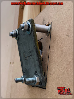
Drew up a servo bracket to fit inside the rear of the eye to activate the upper eye lid. Version 2, fitted better and uses a SG90 servo.


….Pololu still hadn't arrived.

March 5th:
Mike had the angled bracket for the eye, so I drove down to his work for a day of testing and fitting 😄.

We first brought out the three pieces and assembled them together. Mike had marked and colour coded them for easier and future assembly.

We marked the spot on the front and then drilled a hole through. This was the upwards angle point needed. The eye does stick out a fair way from the door when speaking to 3P0, but we wanted to avoid this so as people wouldn’t bump into it when having photos taken. We weren’t happy with the angle either, so the this was adjusted using longer bolts and spacer tubes to increase the angle more.

Here’s a progress picture:

Mike’s a big (tall) lad, so the fact the eye position is not in his head bumping range, is a good thing.

This fitting, figuring out, re-fitting, then cutting down the tube lengths, drilling locking location holes in the tubes…… took us about 5hours!!

Once finished I had started cutting down the tubes to fit. They didn’t need to be as long after all.

The tube can now be finished off with painting. And a collar/back plate, needs to be drawn up and printed to cover the whole in the wall.

I got home and made a start on primer painting the last pieces, the tube ring and the PVC tube.

Late March 18th:
The back plate had been printed and painted, along with the rest of the last pieces.

The PIR sensor unit that will hopefully trigger the sound and lights (& servo if the boards arrive in time), needed a housing and a position for it to be mounted in. I wanted all the electrical/electronics to be combined into one unit for easy of assembly, so using a design I had already, I modified it into a sensor type unit that can be pivoted and rotated to best suit the location.

I had also read that narrowing the line of sight helps with the sensor not triggering unwontedly. So the sensor housing has a tube over the front of it.

Early April:
With weeks left and no sign of some of the electronics, I have had to admit slight defeat. The set up for the sound and light activation wasn't working when triggered at the same time??? So it looks like they will have to be separate. Tried getting the servo to operate, but the circuit board is not a momentary switch, when I saw it I thought it moved and returned the servo when pressed/released.
This is testing the PIR sensor to trigger the sound via relay switch (centre of picture). PIR on the right.

There will be an event report that has/will follow detailing/reviewing Celebration. This will include more photos etc, so don't forget to scroll back through this Blog, like, share etc. I hope this behind the scenes was of interest to you. Please leave a comment below

The wiring is there for future upgrades, probably better suited to an Arduino set-up, and for someone who knows what they're doing.

All in all, I am 90% happy with the finished item, minus the not working bits.

I hope you enjoyed attending Celebration and that you were able to have photo's taken with the display.


November 20, 2021

GOUD-4 project update


 So after the event at The Galleries, Bristol. There were a few things I wanted to sort out with G4.


These I’ll be covering on this Blog and the Mouse Droid forum, as GOUD-4’s Blog doesn’t seem to attract much interest/traffic. I’ll be transferring all of the build details over onto this Blog as a new ‘page’.
  • Sound system set up.
  • Panel activation….
  • 3D new parts.
3D printing:
I needed a new bracket/holder for the new ESC (electronic speed controller). So I measured it up and drew up a suitable holder, which also incorporated the on/off switch.

Also drawn up a speaker bracket, just need to print it.

Sparkfun sound card bracket:
I drew up this bracket to hold the SD card reader sound card.

I already had a bracket holder for the voltage regulator.

Transmitter/receiver:
I eventually found out what was causing the remote signal issue.
See Transmitters - Volantex Exmitter's post for details.

Sound system:
I had started this a while back, but was pressed for time to complete. Now it’s time to finish what I started. Been waiting on a relay switch that can be activated via the transmitter, similar to how R5’s sound system is triggered. I’ve soldered up the connectors, I next need to fit all the components onto a board and find a spot to install it.

Top Panel opening:
I also have the top opening panel to sort out. The bracket is printed and the servo is fitted into it. Its then just a case of connecting it up to the receiver.

October 26, 2020

Sounds for Droid 2020 - 1.8 installation

Made up a new bracket for holding one speaker, out of some MDF wood. The prev one was perspex and was attached to the old sound board.

new speaker position

I may mount the second speakers in a rear position.

Continuing on with organising the wires, the slip ring underside wires are always annoyed me as they are stiffer due to less strands. This makes it awkward reaching inside as they get in the way. So I decided to cut them short and connect new, more flexible cable. This will also be yellow to match up with identification of the voltages, yellow being 12v positive.

slip ring cable modification

Next up was to install the sound board. I changed my mind about which side to mount it on. Decided that it would be better over on the right hand side. I needed a spacer block, so cut a small piece of wood, marked the boards fixing hole position on it, then drilled clearance holes and screwed the spacer block to the frame.

spacer block

Next up was to then mount the sound board to the spacer block.

Sound board fitted to spacer block

I de-soldered the red power cable on the sound board and replaced it with a yellow one. I had some yellow heat shrink to cover the red wire for the Trading Card Dispenser electronics box.

Next up then is to connect the speaker, route the servo lead which operates the relay switch and test out the amp/speaker. Also need to look at where best to fit the volume control knob.

May 14, 2020

Sounds for droids 2020 - upgrade 1.4

After the last testing and the feedback created being a nightmare and the ground loop isolater circuit just wasn't doing anything. So rather then using standard speaker wires, as can be seen in the video in my last post, I cut down the leads from the RCA leads and swapped the standard cable over for these.

OTHER WORK
Since then I've been working on creating 3D printable enclosures to house all the pieces.
Sorting out the orientations of them so will post up once done.


.......3D printed parts for the utility arms have been done
by a work college and are now in the post to me.
Thanks Will.

April 16, 2015

Sound board - installation complete 1.1

Made up some wood location stands, cut slot's into them and screwed them to some MDF base plates. These were then screwed into place.

I then made up a cardboard template of the metal bracket I wanted to make to secure the top of the board. Cut, drilled and then bent into shape, marked position on board and drilled a clearance hole for a bolt, washers, spring washer and a butterfly nut, to secure in place.

I then finished off some more wire's, soldering and connected these back up to there respective terminal blocks.
R5-D4,

R5-D4

R5-D4 sound system
The top securing bracket can be seen better in this image.
This lot took over an hour to complete!

March 16, 2015

R5-D4's Sound system installation

Started work on drilling holes and positioning components. I sort of know where everything should go, but am still waiting for the 12 channel remote, to be able to finally know what space I need.

I'd ordered some PCB nylon spacers 12mm long, but these were too long for the 20mm bolts and ny-lock nuts, to go through the Amp's holes and the Perspex board. So had to cut the spacers in half. Not the end of the world as means I've got twice as many now lol.
R5D4 sound

Marked and drilled holes for the four bolts & one hole for the power cable to come through.
This was as far as I got. I had to re-solder the fly leads on the original digital volt meter as they had broken off through use. I then applied hot glue on all three digital meter's contacts, to prevent strain on them.

SPEAKERS
My speakers came, and it's been sooooo long since I've bought car speakers, I forgot they often come with speaker wire too lol, bonus. These are Pyramid 3.5", 8cm, 240w Coaxial Two Way's.

I plan to have them mounted onto the main electrical board via a second stand off board.
First, I marked out some perspex and drilled/bored out holes with my adjustable cutter. Machined up some aluminium spacers for the screw positions.
PIC of perspex with speakers fitted - still W.I.P.
Sound system for R5D4Sound System in R5D4

Sound system for R5D4

The board still needs to be to size suitable and fixing holes drilled for it to be attached to the main board.

February 25, 2015

R5D4's sound system 1.1 - Audio FX Sound Board

Have ordered more components for R5's sound system.

The 'Sound Board' I've ordered is an alternative to the normal one used by most builders. But at half the price, and after I'd checked with our IT guru's on the UK R2 Builders Forum, I was assured it will do the same job.

It's not MP3:
  Quote: The sound board is designed to be simple: it does not have polyphonic ability, can't play MP3's (MP3 is patented and costs $ to license, so this board uses the similar but not-patented OGG format, there's tons of free converters that will turn an MP3 into OGG), isn't reprogrammable or scriptable, and you can't have any other kind of trigger type. However, there's a good chance the project you want to make will work great.

Also bought some speaker cable, for the speakers (still to buy) but also for connecting up the sound card to the 12 Channel remote unit, which I had ordered, but then received an e-mail stating there were quality issues with the units so a refund was on it's way....

September 17, 2014

Fire Extinguisher 1.3 - 'Bad Motivator'

Flashback date: 24th June 2014
So, this was my first idea for how to get the effect of R5's Bad Motivator blowing.
R5's Bad Motivator
Then I thought, why stop there!?!?! So my next thought was to mimic the effect from the film, as best as it could be lol.
R5D4 bad motivator, ANH


R5's Bad Motivator
With idea 'B', I'd have extra vent points, positioned around the edge of R5's dome.
On activating the system, Mist would be ejected out of the Motivator pie hole and from around the edges of the dome, along with the sound effects of R5's motivator blowing up.
~~~

Roll on a few months and I'm now starting work on how to 'pop-up' the Motivator & vent mist at the same time. The sound etc will follow.