February 2024:
It’s been a busy month!
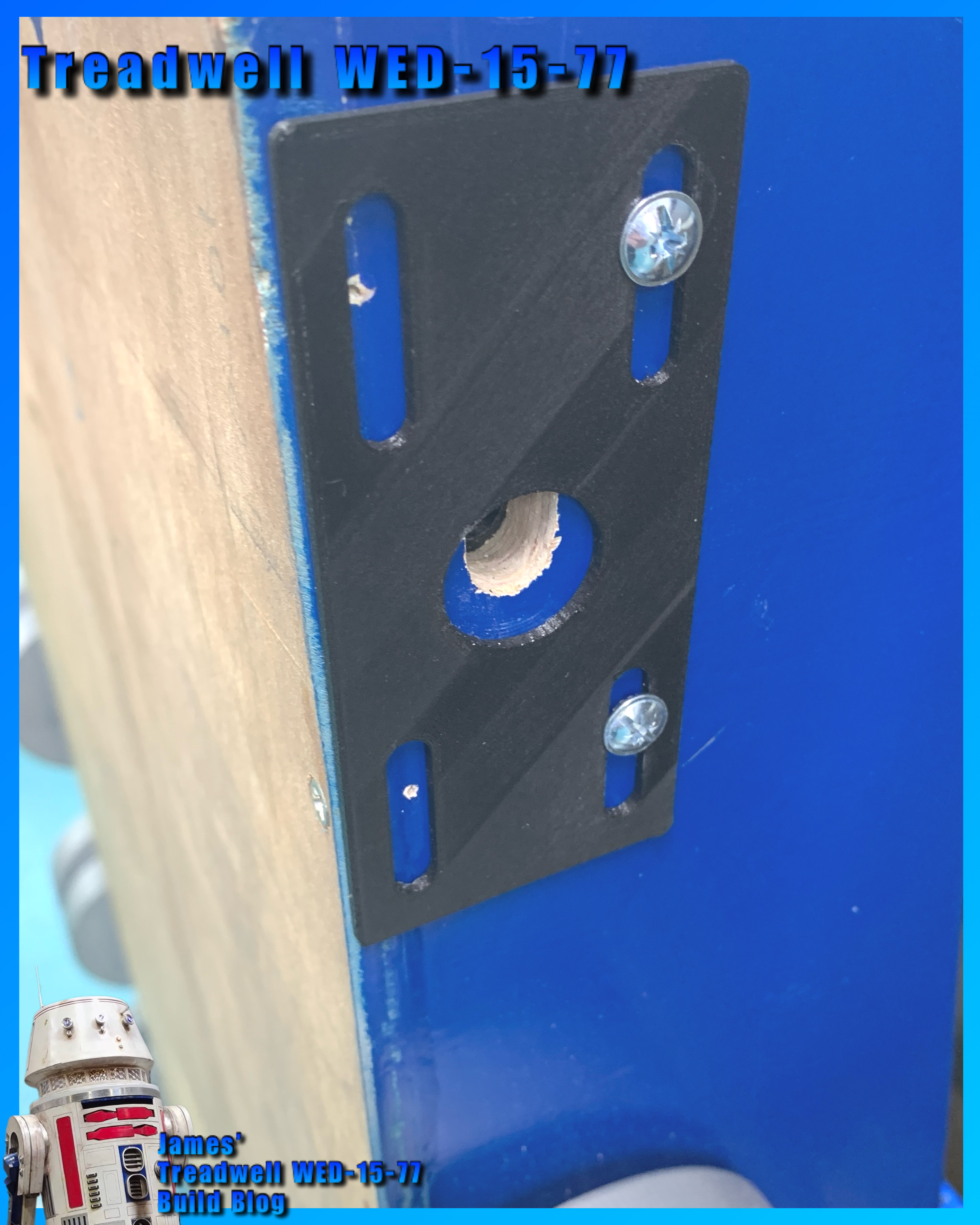
At the beginning of it, I finished machining the last two axles (front). These have M10 nuts to secure them in place, with their 3D printed brackets, picture below.
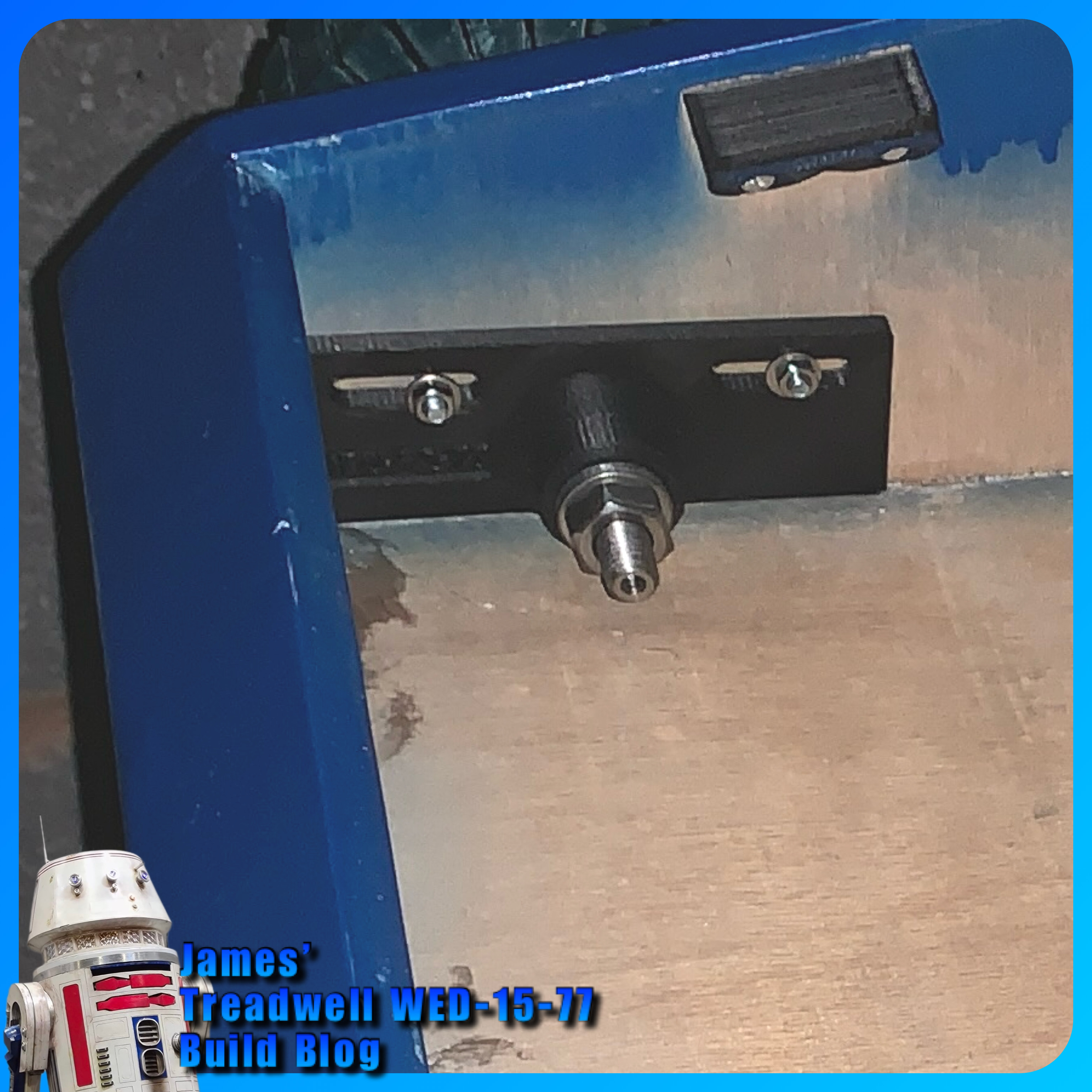
Here’s a picture of the axle securing screw, that locks onto the flat on the axle. It threads through a captive nut that slides down inside from the inside wheels face.Ordered some more blue paint. This is for the newly cut edges. I’m thinking of also spraying the inside panels as well with what’s left.
The second motor arrived but the brackets still haven’t, should of been here by the 12th February at the latest..... Got a refund, so had a go at printing my own version in some PETG material.
Heres the first proof of concept print.
This was dimensioned off the tech sheet, but is too high for the shaft centre line to the axle centre line. So had to reduce the height and also add a separate base, so the print orientation would give its best strength. These were then superglued together. The base has recesses to match the motors diameters. Printed a second test bracket to check for strength.
Three different front bracket versions later, and we had a winner.
Bracket no2 was then printed off.
Unfortunately I didn’t account for my hand drilling of the base side holes lol so the second bracket was slightly too high for the axle centre line. No problem, I just trimmed out some of the wood from the base inside.
This was done using a craft knife, to score, then slice a thin layer off at a time. Very time consuming with a lot of concentration so that the blade didn’t slip (fingers). I also didn’t account for the extra side strengthening piece I’d added for the front to base.So this also had to be scored and trimmed out (not shown in the picture).
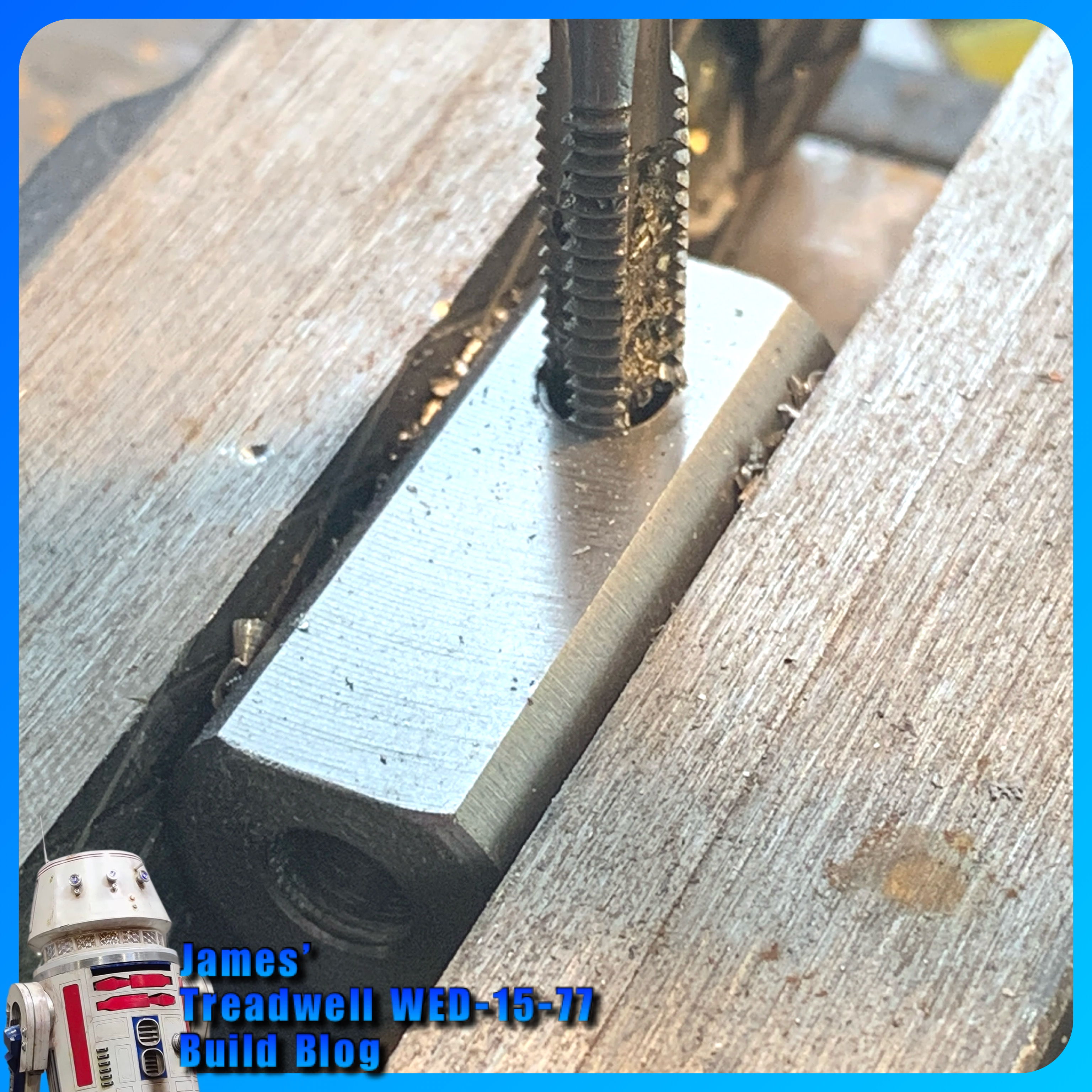
The new motor no2, needed a coupler. Below is me tapping an M6x1 thread for one of the two locking grub screws in the coupler.
3D Printing:
- Printed off some more wheel spacers in polypropylene.
- Drew up a mast base support plate. This was an idea I had to help support the bottom of the mast and add rigidity….. on re-test fitting the mast afterwards, the lower structure was already strong, but this does help. See picture below.
- Forgot to mention, the battery location brackets I drew up and 3D printed last month.
- Drew up a new receiver unit to secure it to the board, see control board picture below.
- Motor brackets, see above
- I made some covers for the wire holes, to make things look neat.
- Drew up some control panel supports & printed.
Mast base support.
Marked and drilled the two holes. I had included hexagon recesses in the 3D base plate for the M5 nuts to help secure. These will be swapped out for Nylon locking nuts.
You can see the opening in the PVC tube for the servo cables to come out from. I did this rather than slot the bottom of the tube (first idea) so that it retained its strength once over the support plate. I didn't think about just leaving a gap in the base support 😖😖😖. The servo leads will be made shorter and have a connector block.... more on this later. See more on this below ‘Servo connections’
The two countersunk bolts underneath the base.
Electrical:
Once I’d decided on the battery location, it was going to go in the rear, but decided the front might be better, plus more space for the control panel and for the motors. I still need to make some brackets to secure the panel.
Bought some 14 swg cable, as the 12 swg looked a bit overkill compared to the motor wire.
Servo wires:
Whilst re-installing the head cables into the mast, the arm servo lead got caught and unplugged. This wasn’t the end of the world, I simply unscrewed the arm box cover and pulled out the cable. I had thought this might be a future problem, just hadn’t gotten around to fixing it. So now it’s secured with some clear heat shrink. ‘A’ for arm servo.
Finally, slide cable back down inside of tube.
Control Panel:
I used one of the left over boards from the Head Box build, as a panel to mount the speed controller, fuses, switches, receiver, and sound system boards. This is the start of the panel work. The two toggle switches (top right, above the Sabertooth speed controller) are off an old transmitter. One is for power and the other is for turning off the sound board.
UPDATE: A new power switch is to be relocated to outside of the body for quick access.
Here’s the beginning of the rear wiring:
The 12v power comes in from the top to the switches, then down to the ‘IN’ power terminals on the Sabertooth speed controller. The two ‘OUT’ red wires then go to a fuse socket terminal.
The cable will come from the fuses to the motors.
Not that it will be seen, but if it looks neat and organised, it’s easy to troubleshoot etc….. Yeah…well….that was the intention 😂, but decided that the front should take priority, looks wise, as the assembly progressed.
Almost completed front panel:
I drew up and printed off some supports for the board. They are angled to mirror the body lid panel. I sunk in some M3 brass inserts and made some finger screws.
I 3D printed some covers to hide the cables as they passed through the board.
These can be seen in above picture.
The Adafruit sound board, (yellow wires) with its dedicated voltage regulator to its left, is next to the amplifier on its right. I needed to re-wire the sound components as this was originally designed for Jabba’s gate keeper droid TT-8L/Y7 for Celebration Europe 2023 (link to Blog build post part 1 of 4)
Servo connections:
The servo leads needed to be cut short so that they wouldn’t get trapped when installing the mast through the hole. I had seen what I needed months ago over on Thingiverse (link). You fitted one side of the servo connectors into the block and the other side into a ‘plug’. I downloaded and test printed them. This worked but I needed a bracket to hold the block in place inside the tube. My cylindrical tube adapter on the right in below picture.
These idea worked, but I found I didn’t need a full circle, after I accidentally snapped off one of them lol.
As I wanted this to be a one piece unit, so I drew up my own bracket and plug holder. The bracket worked, the ‘plug in’ part needed some small alterations. Don’t think I actually need this part.
The following pictures show my servo connector version. With shortening the servo wires, I then had to re-crimp the sockets and plugs.
Pictures don’t show the plug part, just what the socket part looks like. The cable plugs shown are to remind me which lead is which, until I get them labelled.
All four leads fitted into the socket inside the tube.
Proof of concept works. Next is a version that fits better within the opening.
Next was the top servo cable securing ring. This was to prevent them from dropping down inside the mast, as it kept doing lol. The cables slot through the loops and then I added a small cable tie to help prevent the cables slipping down.
Detail's:
Another detail I need to continue, was on the front panel. It needed to have pop rivets added to give the illusion of them being metal plate.I need to add more to other areas of the body.
_ _ _ _ _
\°00000°/
- - - - -
Tracks:
I really want to have a go at moulding the tracks.
I was going to wait till I’d tested out the temporary display set I had. Unfortunately one of them broke when re-fitting onto the wheels.
Before the temp track broke, I had a go at 3D printing the guide teeth in Polypropylene. These were too stiff, so a redesign was required, but as the temp track broke, I decided to focus on other parts of the project instead.
The idea was to have a thin strip of 3D material linking the teeth, hopefully, helping with retaining them on the track.
The supplier I bought the rubber mould material from, supply in 2Kg , so I’ll be ordering this next along with colour pigment.
Photo opportunity:
Co working was leaving (end of February) & wanted to see the assembled droid.
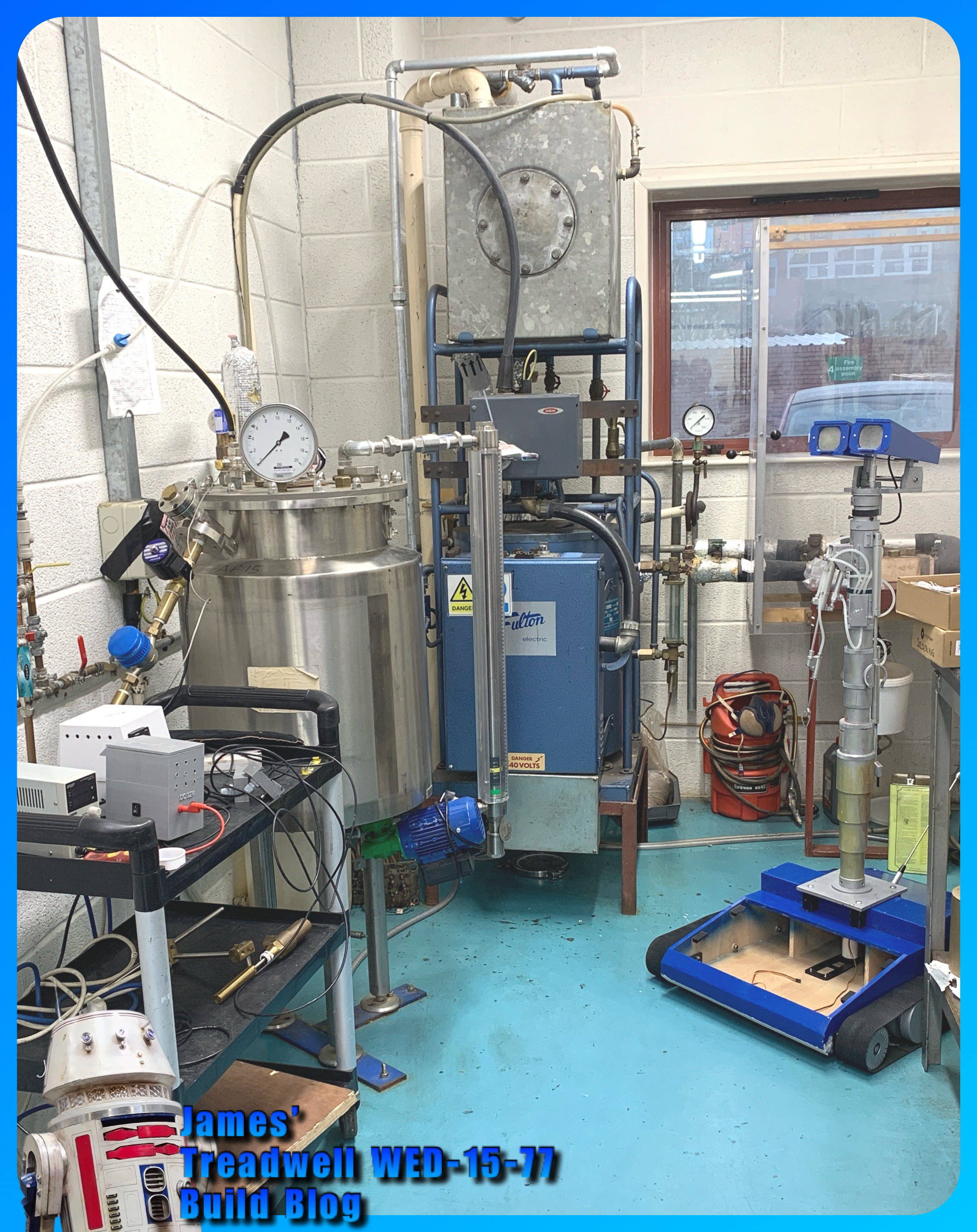
Took this first picture of it about to start working on repairing some machines 😂👍🏽
And here he is by himself:
Still plenty to be done so stay tuned …..