Showing posts with label servo bracket. Show all posts

January 11, 2023

Treadwell WED-15 droid build : Part 9 - mast, claw arm

 🎉 Welcome to 2023  🎉


Build updates:
  • New servos
  • Claw Arm & Carbon fibre rods
  • 3D printed hose clips
  • Mast update
  • Ordered some filler primer paint
New head/eye servo:
One for the eyes. I’ve also redrawn up the piston part of it. The linkage between the two eyes has also been modified.

Claw arm:
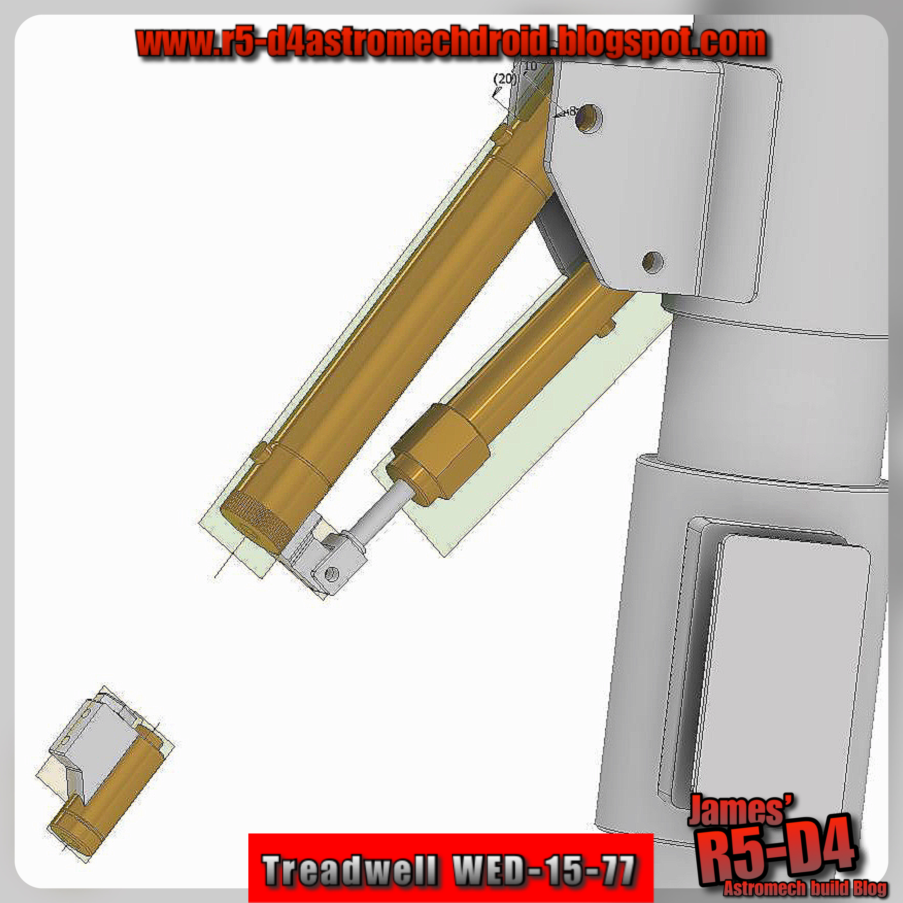
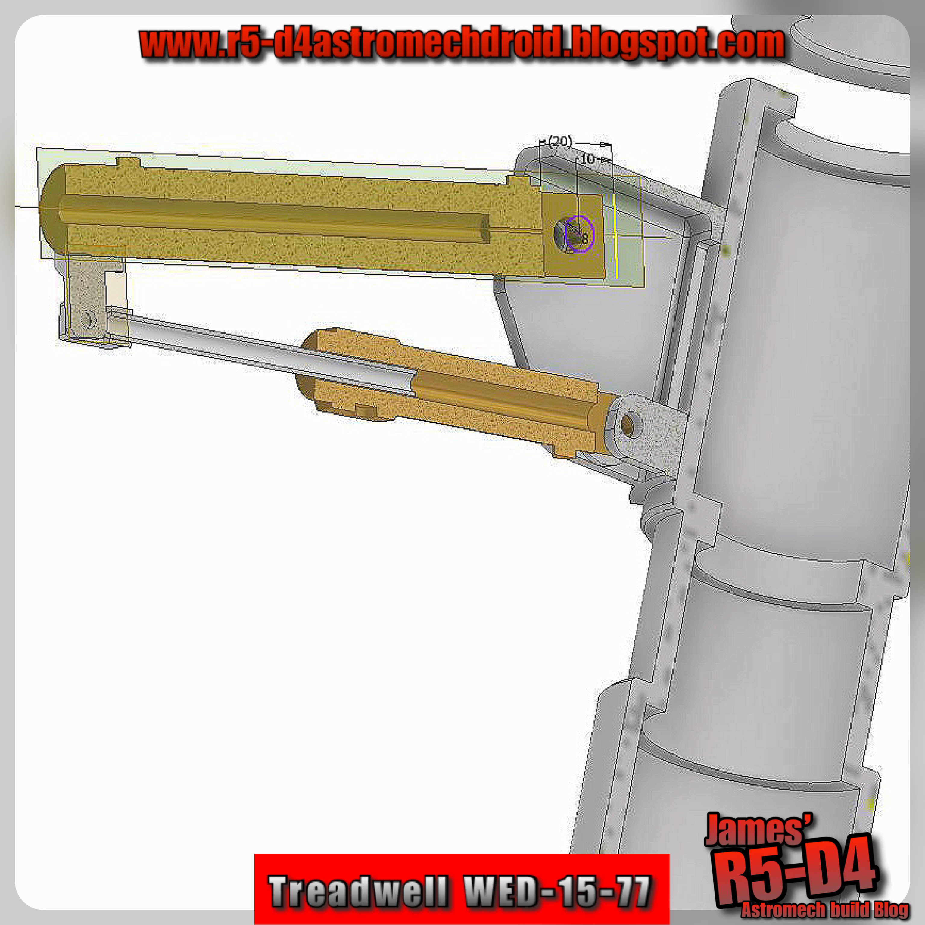
Back in work Jan 4th, and drew up first arm bracket that attaches to the mast. Printed it off to see how it will work. Am impressed lol, it looks good and is functional to, the arms pivot well & the test ‘tube’ slides well in the lower ‘piston’.
Here’s some pictures of the CAD work, inc half section views.
3D printed, 3D design, WED-15 droid

The end unit which the Claw fits into has been redesigned/updated. It now looks more like Paul6700's. I've also been working on a way to get the Claw to operate as well. Had to 3D print off a small adaptor, which then attaches to a spring, more on this in a later Blog post, when I actually get it all working lol.

3D printed, 3D design, WED-15 droid

Half section view:
3D printed, 3D design, WED-15 droid

Here’s a test assembly:
3D printed, 3D design, WED-15 droid
The steel tube (in above picture) will be replaced with the carbon fibre tube (before it arrived). This will help with the weight for the servo to lift the assembly.

Took me a few attempts to figure out how best to actuate the movement, but I think I have a working idea.

Hose Clips:
I drew up & 3D printed off some hose clips. These can be seen on the original version. The original was operated by hydraulics', but not knowing what they actually used, I drew these up to just clip over (to be eventually glued) in place to hold the 'hydraulic' hose.

Mast:
The last lower sections of the Mast have not been printed yet. Before they get glued together, there are details that need to be included & holes to be cut.
Drew up and printed off a SG90 mini, servo bracket. This will be housed inside the mast, hopefully to actuate the claw.

Filler primer paint:
Visited my local car store (Halfords UK), and the price for one can was £10!
So I went on eBay and bought two (better) can's for the same price!

October 20, 2022

Life-form scanner - R4-D4 - part 20

June 2022
Back in June, whilst I had R5’s bad motivator setup out of R5’s dome, I thought I’d refresh my memory of where I was with R4’s Life-form scanner.

After recently salvaging parts from a broken 3D printer, the parts gave me a better idea of how to operate the lift system.
So this version will be belt driven.

I needed to design some new parts so that the original setup could still be used.
A new lower bearing holder was drawn up and 3D printed. This clips over the lower bracket and has a locking screw to secure.

The main lift unit had a bracket added to clamp the belt onto.

The upper unit had to have a new servo holder designed up as it needed to be turned 90°’s. This has a location tab and a securing screw.

July 25th
Test printing done and then some more redesigning. The bracket needed some work done after all, so it had the lower bearing included in its update. This bearing holder also needed to protrude more to allow clearance. This also means it replaces the ‘clip over’ version.

Next up was the main lift bracket.
This was also modified to protrude more, for the belt to be aligned and to allow clearance and full travel up to the top.

October:
With the progress made with the Bad Motivator setup, these will be included on here.

October 19, 2022

‘Trading Card Dispenser’ control box - servo switch controlled


October 1st
Back at the beginning of the month, before I fitted the remote control, inside my transmitter, I had thought about utilising the servo activated switch module, that I’d bought for the GOUD-4 droid.

So I combined the bracket I’d designed up for it with a new saved version of the control box base.
wrong RC servo switch.....

Some other modifications were needed to accommodate the alternative model timer circuit board I’d bought, as well as doing away with the lid's side clips and replacing them with a brass knurled threaded insert. The lid section needed alterations to and the design of the slots was simplified. I did away with the LED ‘on’ indicator as it wasn’t necessary.

Have been test printing both in work and at home. It was good to use my printer that’s not been used in over a year. Dusted off the Tevo Tarantula Pro (Orange), fired it up, first print, perfectly just like always.

Probably should mention using online program, Astroprints for creating the gcode for printing on the Tevo.

UPDATE October 2024:
The RC servo switch seen in the above images was the wrong one!
I've updated with the correct RC switch, so for more I'll be posting up a new correct set of parts & 3D printable components. 

October 15, 2022

R5’s Bad Motivator : reincarnation (Part 2)


March 2022
Planning out the electronics/electrical connections etc.

This has been the most concentrated effort of work to get things ready for Birmingham's event @MegaCONlive [26th March 2022].

….well…..I got it working on the bench, but there was a problem once installed in R5’s dome.

The smoke system worked ✅
But the magnetic actuator didn’t have enough to move the motivator assembly ❌

So back to the drawing board & a new lighter motivator assembly .........


October 2022
I eventually returned to this project as have time. I thought I’d try out an idea that Brad 'BHD' had a few years ago to activate HIS bad motivator’s on his droids.

It utilised a servo, pivot arm and a track system. His droids are gone, but his webpage Blog is still lives on 😎👍🏽


For lightness I dug out a rail and bearing carriage I'd salvaged from a 3D printer.
Next up was to measure the carriage’s holes position, so that I could draw up in Inventor CAD, an adapter to a-fix to it for the Bad Motivator. I then needed a bracket to secure the servo to and also the rail. So again I CAD’ed up a design and 3D printed it off. It was a Friday, so I knew that this would have to be ‘modified’ lol. Sure enough, with the help of my soldering iron, (melting plastic to reshape areas, the servo fitted into place.

I’m using a metal gear servo for strength, the new motivator isn’t overly heavy, but just to be safe as it will see a lot of action.


As this setup is in R5’s dome, my standard arrangement to activate the bad motivator, is via a remote control fob.
I have been toying with and have tested out using, one of the other transmitter’s receiver’s (I have a few spare and connected it up using the last free channel on my transmitter). This is still a work in progress idea.

After printing the components, I test fitted the assembly unit into R5’s dome, only to find that the rail was further over than existing setup. The new assembly is fitted inside the dome, the old one, resting on the top of it. the 'white' component is the original 'Bad Motivator' location piece, the inside 'black' component is the new 'BMs' location piece. So I had to do some CAD alterations.

The next set of prints worked much better, fit wise. On test fitting, I had trouble with the actual motivator fitting up through the pie hole, without it catching on the new rail. This was due to orientation.

I’ve always accepted this motivator design as (at the time) was the only version available. But I think its now time I stopped wrestling with that nagging feeling and CAD up the motivator ‘that I envisioned years ago when I first sketched it up from what/how I saw it from screen caps’. (Said in Moff Tarkin’s tone of voice 😂).

…….So that’s Mondays project!

Next was to install the brass inserts, drill a few holes to secure parts and wait for a dual relay switch to arrive.....

March 06, 2021

R4-D4 dome - Life-form scanner - part 18

Re-wire switches:

The two switches that I had, just inside the opening of the dome, needed to be relocated to just clean up everything. These switches controlled the 'fake' electronics panel LED's as well as the Holoprojector light LED.

Am thinking that the Holo LED will be controlled in the future via a remote, to increase it's brightness when needed.

.....next up....

Painting of parts:

I had applied filler primer and once dried, sanded lightly the components for the LFS system.

I wasn't 100% sure what colour would be best for the internal components of R4's dome, but as I had already sprayed the lid panel matt black. I decided that the main inside panel would work better this colour than say white.


The lower servo lift was also sprayed up black.
The servo cover & LFS screen, both got silver paint. The internal panels and top, got a dusting of silver to help highlight the details.

The screws I had inserted to keep paint out of the threads, I decided to keep, as they blended in better than the clean versions.

I then applied a clear coat and then some black to add to the weathered effect. The orange primer also appears to show through in some places. This isn't as bad as I first thought lol, as it actually looks like sand in the crevices etc..... result!

I then installed it all in the dome.


The bracket can be seen installed. Up next is finishing off the electrical install and then the Pololu controller and electrical hook up.

R4-D4 dome - Life-form scanner lower bracket support - part 17

 I didn’t want to glue the two rods in place as this may of effected the sliding of the servo bracket by misalignment. But I needed something to support the lower bracket and help keep it all inline.
R4-D4

So I did some measuring and drew up a another bracket that will bolt to the lower bracket and then screw to one of the wood neck ring supports. The carbon fibre tubes are loose fitted and allow for slight movement so as not to jam the guide.
Must be getting better at this :D as it's right first time! lol.
Had to order to new bolts the right length for clamping parts together.

Next up was spray painting the other parts.

February 26, 2021

R4-D4 dome - Life-form scanner final design - part 15

 Sooooo...... :D yes, I think this is THE final incarnation of this 'little' project lol.

I suppose this version was inevitable as this project has progressed, but the intention was to just have an independent set-up. So why have multipile components, with possible alignment issues etc. This design now incorporates the Pie hole panel and the life form scanner as a one piece unit.

life form scanner, r4d4, pie hole panel,

The colours show the (modified &) combined components.
  • ORANGE = modified Pie Hole Panel unit.
  • BLUE = upper servo lift bracket
  • RED = upper LFS bracket
  • YELLOW = LFS bracket cover
  • GREEN = additional greebles.
The PHP unit had to have surgery to allow the lower bracket/guide to travel all the up to get the most travel for the LFS. The inside panels also had work done as there was no need for details on some of them due to the face that when the lower bracket is raised, it would block them from view.

The RED upper bracket, was a hacked previous version, but needed something to top it off visually, so the cover was added. This is also one of my old greebles that I copied and modified to suit.

This all still works with a upper 360 deg servo and a length of cord.
life form scanner, 3d printing


I need to increase the length of the carbon fiber rods and shorten the a aluminium main LFS rod.....may switch it over to also being carbon, just to be prepared for possibly being grabbed.....which with it being so thin walled, would easily bend/break!

With the finishing touches done to the design, it was time to print!
3d printing


I've created this short video, link to my YouTube channel.

As you can see, the assembly was installed inside my R4 dome. This is still a test fitting, as the pieces need to be painted and also the electronics/electrical also need to be finalised, but am really happy with how this is turning out.


And viewed through the open lid

Still some minor things to do, like design a cover for the servo which will be visable, also the support rod, this is a 'spring' at the moment, may need to be a bit more substantial. Also looking at repositioning the mini switches that are inside the dome to be mounted on the top face of the inner panel. These only control the LED's.

#3dprinting #3dcad ##tevotarantulapro #3ddesign #r4d4 #astromech #ukr2d2buildersclub #droidbuildersuk

February 21, 2021

Life-form scanner - carbon fibre tube part 14

So did the redesigns, and printed them off and all worked great.
Life form scanner installation
But, after installing everything, there were a few teething problems with the lowering of the base servo as it was still getting jammed on the rods. I think this is due to the centre of gravity. So back to the design board again.

Life form scanner lift system
Not shown in the above picture is a support rod with a ‘sprung’ guide for the main LFS rod.

The upper servo holder had the two rod holder positions moved out so that the strings pull was more central to the rods.
3D printing the brackets
This new lower base servo holder had additional guides added to the upper section, the servos position was moved closer to the two rods and the hole for the string was centralised between the two rods.
Lower servo bracket
Test printed the two new parts and assembled all together.....yes it works with no sticking! Brass threaded inserts added.

I then test fitted the assembly inside the dome and placed the dome on R5. This was to check clearance and how much the rods will need to be shortened.
Test install in dome on R5’s body
The support rod & spring can be seen here supporting the main rod. The carbon fibre tube needs shortening and also the receiver housing (yellow) may also need repositioning.

February 12, 2021

R4-D4 dome - Life-form scanner - carbon fibre tube part 13

Have been working these last few weeks on redesign’s for the lift setup and also on another project....

Life form scanner

After a chat with a few builder friends about the aluminium wall thickness problem, Mark suggested trying carbon fibre rod as an alternative to the aluminium tube, for the lift/guide on the LFS unit. Ordered some 6mm O/D tube and it arrived from eBay within a few days. On receiving it I found it wasn’t as cylindrical as I was expecting, so I had to update the hole/guide sizes, not once but a few times. Printed off a few test pieces to check compatible sizes and then more test prints.

I had to go with a slightly larger bore on the guides rather than the original tighter fitting option, due to the carbon rods O/D.

Was still experiencing issues with the sliding. Possible alignment with the rod attaching to the lower servo bracket perhaps??  It was ok lifting, but got stiff near the top, which then prevents it from lowering under it's own weight....

This just wasn’t working...... So, I had to came up with a new design. This one now uses two sliding rods for the lower servo bracket to be guided on. I’ve also flipped this bracket over so that it’s guides support better on the rods from the underside. This all now works smoothly again lol.

With this new design, meant that the fixing bracket to the dome needed redesigning as well.
I also needed a new lower stop bracket, that linked the two tubes together but would be able to flex under the tubes being stretched if miss-alignment was an issue. I was really excited that it actually works.
Lower spring stop

Next up are a few more smaller changes and a new additional support for the main LFS tube.

February 03, 2021

Life-form scanner electronics part 12

January 24th 2021
Found a ‘box’ on Thingiverse for the Pololu control board. So that got printed, and it’s  a perfect fit!

Next up was something I’ve sort of been looking forward to.... the Pololu 6 servo controller. Downloaded the program and plugged in the controller board along with two servos I had to hand. You also need power for the servos. The instructions online are good, but ..... I personally find watching/listening to step by step guides, is better at understanding a process. And I had a short sequence running in no time at all. This is going to be fun setting up the life-form scanner setup.

February 2nd 2021
360° servos have also now arrived & have been tested.
360 deg rotation servos

Also the ‘Y’ servo lead’s came to.
Now to get on with the fine tuning.

January 20, 2021

R4-D4 dome - fitting Life-form scanner part 11

 Installed the LFS into the dome. Two counter bored holes were drilled to allow the two countersunk head bolts to sit down inside the edge, allowing the lid to be closed flush. These have nylock nuts on the inside.


The aluminium tube thin walls are easily bent, ever so slightly from being man handled and installed..... think these may have to be replaced with either solid bar or steel, if I can find the size. Also remembering the first tube I bought had a thicker wall, but was a lot more cost wise. I would of liked to (of) kept the tube as LED wires could be run up inside.

Of course I had to do a manual test of everything. The lift worked, but not as smoothly as previously (slightly bent tube), but the principle still works. The lid panel was already opened lol :D I then powered up the servo tester to 'sweep' the LFS.

Next is to look at the Pololu controller and figure out the best way to activate everything. Am thinking I might not need the micro switches.......???

January 18, 2021

A Life-form scanner for R4-D4 - Part 10

 So this evening I've been updating:

Life-form scanner assembly list of components

  • the upper servo bracket
  • the lower servo bracket
  • the lower micro switch 'stop'

Life-form scanner, upgraded with micro switches

The upper servo bracket

Now has the cut-out designed in. As this cut into the recessed areas, I decided to do away with them and add the letters ‘L F S’, for a bit of fun :D. I also added some more material to add additional strength, including blanking off the guide tube hole.

I had also forgotten that I needed to include micro-switch holders......after finding them in a box lol. After no luck trying to find ipt files of the micro switches online, I ended up measuring and drawing them up, roughly.

Cut out and micro switch location added

The lower servo bracket
I had to add a lip to the guide sleeve to make contact with the micro-switch when it reaches the top.

The bottom micro switch/stop'
Also needed a micro-switch holder for the bottom. The tube stop seemed a good place to put it. These didn't take to long to modify.

Lower micro switch/stop

.....The real amount of time, was building the assembly seen in the pictures and aligning them to move the way they should lol to ensure that it all works.

Tomorrow I’ll print off these latest versions and then get to install it all in R4’s dome.


#LFS #3Dprinting #astromech #r4d4

A Life-form scanner for R4-D4 - Part 9

 Yesterday I drew up a support bracket that the Life-form scanner [LFS] unit would attach to.

I printed of a test version to check it would all fit. Well it did in the CAD assembly and it did in the dome.

Life-form scanner & support bracket test fittingLife-form scanner & support bracket test fitting

The only thing that has been bugging me is the amount the LFS protrudes out of the dome. I wanted it to go higher.

So after looking at where I could save and therefore increase the height, I removed the coiled wire and lower greeblie from the mast. This meant I could increase protrusion by 40mm out of the dome. This meant the support bracket had to be made shorter, no problem, 20mins on CAD/Astroprint to reduce and produce a gcode file for the Tevo to get printing. Sound impressive, but it’s not lol :D

Life-form scanner & support bracket

The two aluminium tubes needed to be carefully cut shorter to allow the full assembly to actually fit inside the dome. The tubes wall thickness meant holding it in the vice was tricky, but not impossible. The upper ‘collar’ I’d removed earlier, I placed on the end of the second tube to act as a stop. I’ll either cut this shorter or draw up and print another part.

To gain some extra ‘height’ I cut away some of the upper servo holder that guided the main tube. This allowed the lower servos connection to the tube a bit more clearance [see pic below]

Modified bracket

This will be redesigned in on the next update.

The two parts connect well. I’ll be putting brass threaded inserts into the support bracket to secure them together. The bracket has two holes to secure it to the wood frame.

January 16, 2021

R4-D4 dome lid modification - part 6 [YouTube]

 All the bonding on the magnets has set and it all looks good.

I filmed the testing and have just uploaded a short video of the lid panel being opened and closed via the servo tester being hooked up.

Click on picture below to head over to my YouTube channel, thanks.


I’ve taken some dimensions and a cardboard template, and can now look at making up a support bracket for the life-form scanner to attach to.

Hope you like the video.

January 14, 2021

R4-D4 dome lid modification - part 5

 Right, on with the next re-re-design.

This first test print was in two parts, but could be combined into one. I did it as two for best print orientation purposes. Managed to get a good print and the piece fitted together perfectly!

The hinge part got strengthened up to stop any flex. The pivot pin holes were also reduced in diameter. All adding to less play between the components. Meaning, hopefully, less issues with alignment of the lid when closing.

Testing clearance of servo arm in closed lid position.

Test positioning the lid and servo placement

Inside the dome, lid panel and servo test positioning

This will all be controlled with the Life-form scanners activation. But to add some flexibility in the lid servo movement, I’ve test fitted some springs.

Hinge assembly upgraded

Next up was to glue the panel onto the lid panel & the magnets onto the underside of the main lid.

Mixed up some more Araldite to attach the 3D printed part to the wood lid. This was clamped in place. One of the clamps slipped a bit so the 3D part moved out of alignment for where I wanted it :(

Once dried I mixed up a small amount for the first magnet. I placed a piece of masking tape between the magnet and washer so the Araldite wouldn’t bond to parts not required to be bonded.


I then clamped in place.
Servo holder bracket clamped in position

I bonded one magnet at a time to help with alignment of the panel. Once first magnet had dried, I went on to bond the second magnet in place.


.....next is to paint the parts again.