Showing posts with label Plywood. Show all posts

June 12, 2020

Workbench lockdown 2020 organised

Been meaning to sort things out in my garage for years....... well, not much I can do about most of it 😄 but with a bit of re-organising I was able to move one of the domes (R0) off the new shelf and onto an older shelf unit, that now had some space.

So now the R5 is off the bench & with R4 domes.

Next up was getting rid of stuff that I REALLY didn't need. I do keep stuff,with the intention of it possibly coming in handy in the future. Well....if it's not been used by now.... out it went. I went through boxes and sorted out and grouped/organised better all those little bits and pieces.

Clean and clear work bench

The above picture is what the bench looked like flippin years ago when it first got installed. A few little touches to help keep things to hand. The tapes were fitted onto a scrap piece of tube. I made a paper towel holder, mounted about the tapes. Three boxes were secured to the wall back board, which helps store smaller tools etc. [one can be seen top right of picture.

Next up was to make a little removable shelf. This holds two boxes with small components, electrical/electronics, recent small project work.
I didn't want the shelf to be fixed in case I needed the space. So I made it fit over the benches back board and has a support baton underneath.
small shelf


small shelf
small shelf

This word great...... and I started getting carried away with making stuff again. hahaha. I needed a soldering iron station, that I could move around, so after a bit of searching for material under the bench, I made this up...
soldering iron station
 
The solder sucker needed a holder, just so I knew where it was when I need it. The paste tin has raised holder edges to stop it moving forward. Next will be either magnets to lock the base to the bench or the upper back board or location pins.....not sure yet.

The real reason for being able to do any of this was that I had to fit an outside security light. This meant having to fit new electrical cable. So ordered what I needed from Screwfix and got on with the installation. The plus side to this was I was able to add a plug socket nearer the front of the garage.....for use by my workbench. For the last I don't know how many years I've had an extension reel looped over and pinned to the wall to allow power to the bench. Now it will finally be fully independent.

So I just have to finish the electrics and I can start using the bench, much to the relief of the wife as it get's me back out of the front room hahahaha.

December 19, 2018

R0-D4 - new 3D neck printing 2018 - 1.2

More 3D designing and test prints been going on this week. Had to wait for more filament so couldn't set the print to run over night.


Friday's two prints were good, but I needed a bit more thickness, the location tab needed to be lengthened (above picture) and also to be able to secure each piece together.....so version 2.0 was created.....
3D print
Version 2.0

......soon to be replaced with 2.1 tweeked versions lol This will be going up on the printer later today.

October 27, 2017

New Dome - woodwork frame for........ R4-D4

There's still a long way to go, and home life has limited my available free time to actually work on the frame for the new dome. So I took it all into work to try and utilise my early morning starts & lunchtimes to crack on with this build.
This was my starting point, over a month ago now. I'm now happy that this is going to work to be able to share more of my work. The idea for the framework is a modified version, but also simplified version, of what I had seen online by another builder. Credit goes to : Scott Kraft (pithyscott on Instagram)


The side triangle panels will be possibly/temp held
in place with panel pins for the building purposes.
The above picture gives you an idea, the rear triangle is pinned in place.
The centre dowel was to help support the top while I messed around with the uprights.


 There is a upright missing on this side, this is because I need space for R4's holo eye unit to fit. I need to make up a different upright arrangement to support the triangle panel etc.

All uprights temp in place. Next up is to cut out the top plate, to save weight and also give access to inside the dome.

Here's the work for the holo eye box unit. Grooves cut into side panels for the front panel to sit in. Glued up and fitted together.


And the semi completed box unit. There are several different looking box designs, I've gone with fellow UK R2 Builders Colin & Brad (slightly different again).
This simple design suits me.


Next up was to glue in support fixing blocks, seen in picture below.
Still need to add two more to the lower angle face, to make four fixing points.

And here's a mock-up of some of the panels with the holo eye temp screwed into place.

Am on my 3rd attempt at a 3D printed servo holder to fit behind, am 90% happy I've got this sorted now.....well, until I get it all fitted up and it doesn't work! lol

September 26, 2017

New Dome..... &... Feel the Force Day 5

So much for CAD 😄lol, if you don't have the tools to actually carry out the work in the 'real world' 😄 lol. So I used the plans I'd drawn up as a guide.....well, it worked for the last two domes. I have height dimensions etc to work to so it will all fit together 😊
But so far, it's coming together just fine. Just wish I had more spare time at the mo tho.

This pic was posted up on my Instagram feed, which is all Star Wars related stuff as well, no fillers lol.

~~~~~~~~~~~~

Feel the Force Day 5

is this coming Saturday 30th September.
So, check my Instagram, for pics on the day.

Full report next week........

June 23, 2017

R0-D4 dome upgrade 2017 - 1.1

Measured and cut out the ring yesterday. Then marked up where the bearing location studs will go, in relation to the domes skeleton frame work.
And here it & R0's dome, next to R5's dome, for ref work on how I did it etc. Next up was to mark out the recessed parts for the studs.
And then I drilled and countersunk the holes used to fix the new ring to the skeleton frame.

~~~~~~~~~

Next up was to make the stud location blocks. These are thicker than the base ring and help locate the dome securely onto the bearing. I marked the skeleton frame position onto the base ring and then cut out some blocks from 18mm thick plywood. Once I had the position of the stud marked, I drilled out a slightly larger hole so there is clearance allowing for misalignment with the studs. I then placed the ring on the bearing, and using the studs as a guide, I glued the blocks into place.
I did these one at a time. Once the glue was dried, I then drilled and screwed the blocks in place.

Here's the view from inside the dome.
Once these are all in, I then need to look at the new metal neck skin.....

April 12, 2017

Utility Arm pivot points - upgrade time 2017

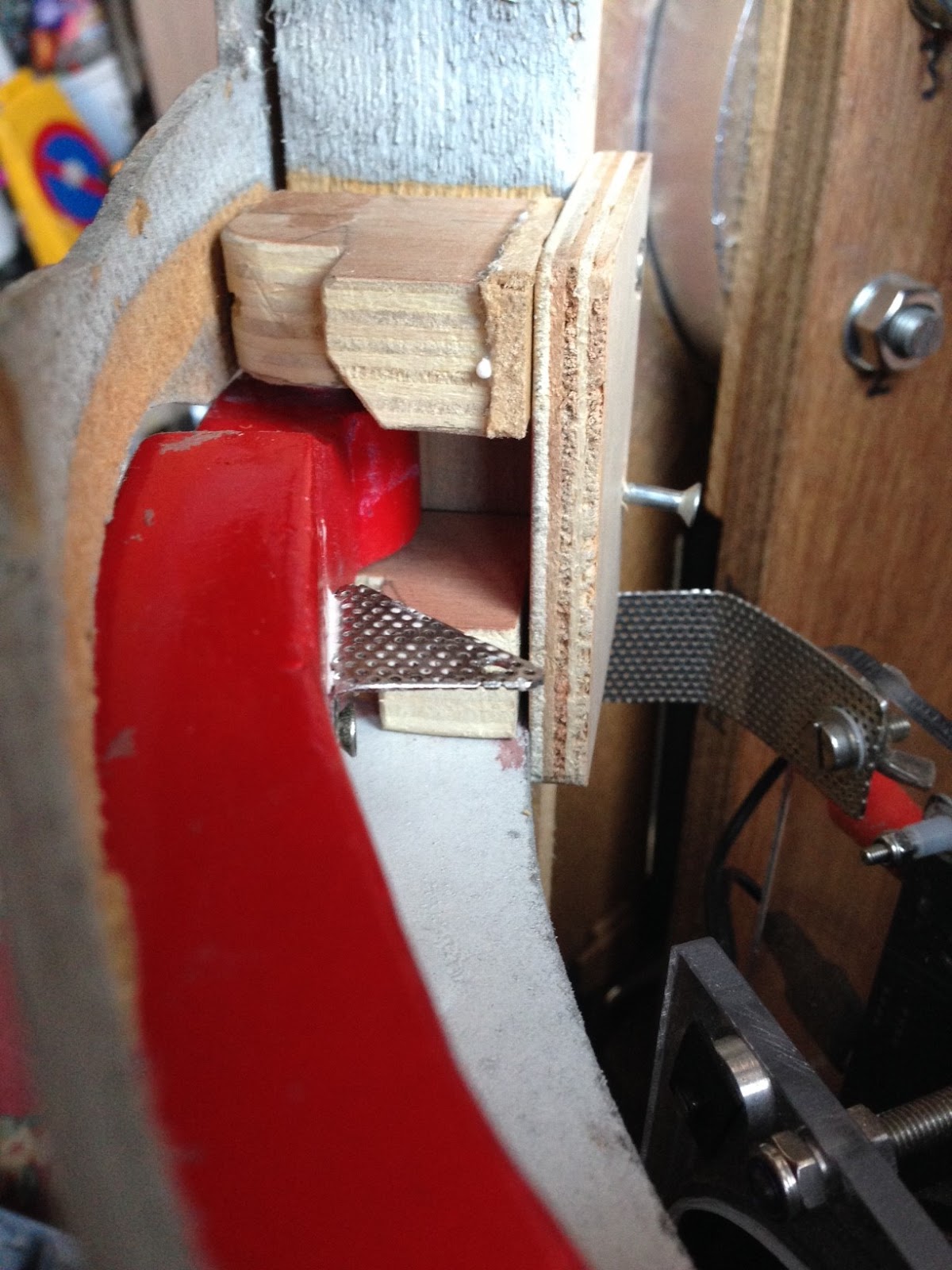
This wasn't on my list of 'things to do', but due to 'little fingers' lol, one of the utility arms, location pads had come loose. So over the last few weeks, this has been one of the other mini projects for R5.

Not bad considering the amount of action they've seen.
Link to post I blogged way back: Utility Arm Pivot pins fixing.

There's the loose pads.
Black mesh screen removed to gain access to rear of arms

Next was to remove the central support piece (the piece above the upper pad).
This was made of MDF.....yes, I hang my head in shame lol. But it was all I had at the time to support the center area.

I then measured up and cut out a piece of plywood which the new thicker pivot pads will be screwed to.
 The pad is temp screwed into place.

Again, just to show position of pad and pivot arm point pads.
This pad is a bit to short, so cut a new longer one.

I may possibly need to modify the servo arms if they are to be fixed to the new bracket. Tho the black mesh will also need to be modified, so if to able to, the servos can remain on it.
not pretty, but will do for now, until servo positions finalised
Drilled and screwed the pivot pads in place.


I also used the old center support to re-cut it out of 8mm thick plywood. The plan is to fit it to the arm pivot pads to make one unit. The 'center support' can be see mid section of the utility arm opening (screw head)

Work then on the upper arm. And as per usual, nothing is ever a simply 'copy/repeat' straight forward process. The pivot pads had to be modified more to:

a) fit
b) have enough material to be screwed into onto the rear pad.

(a normal build probably wouldn't have these kinds of problems lol)

This was achieved and so work could then continue on with primer & this time, matt black paint.

The above pic shows how the pivot pads were 'recessed' under the with of the arm. This was so there was enough material to screw into.
And here's the upper arm pivots attached to the frame pad along with the 'center support' for the arms and the outer skin.

Now these are installed and are a lot firmer, I may need to upgrade the servos to more powerful ones to be able to more the arms. This I'll be testing soon.

April 15, 2014

R5's transportation platform 1.1

I've decided to make R5 a platform for moving him from car to event. After the difficulty I had at Fleet Air Arm Museum's car park surface last year, it would be easier if the platform took the brunt of the possible rough surfaces. It would also be easier to move/steer.

I salvaged a set of 4 wheels (x2 with swivel casters) from a discarded cabinet. The x2 swivel  wheels bushes were shot so had to bin them, but its a start.

Using a piece of 18mm thick plywood, I measured out a suitable size area for R5 to be mounted to. I cut, drilled and screwed to pieces of wood to act as stops for the outer wheel front casters. I then found some 'U' aluminium channel that the scooter wheels fit in. I cut these, drilled and screwed these down next.
R5-D4 transport platform

I didn't get to mount the fixed casters as I have run out of M8 bolts, these will screw into M8 T-nut's that will be installed. This is a job for Tuesday.

I dont want the platform to be to high off the ground, so after seeing a similar platform, the fixed casters are going to be 'recessed' into it. Measured and marked holes out. Then got to drilling and cutting out with jigsaw. Next I bolted the casters into place.
R5-D4 transport platformR5-D4 transport platform

R5-D4 transport platform

I was going to put casters on the front....no.....rear of the platform, but after thinking about it and the fact with no brakes, R5 could do a runner, I've decided to just put a 'rest' to the back face.
That's next stage.....

Hopefully I'll have it finished by April 26th 2014, Corsham Sci-Fi Fun Day.

November 07, 2011

Main Leg - Ankle thickness

Lunchtime I cut out the extra pieces needed to make the ankles the right'ish thickness. 8mm Plywood was used.
Before

Two of these will be cut shorter, as they will be going on the back face of the leg ankles. Only two per leg. Hope to have time to secure these to the leg tonight.

September 19, 2011

Leg cut out & painting components.....

1.5hrs to mark out and cut out first main leg. Three pieces thick, two 18mm + one 8mm = 44mm thickness [guide dimension only]

Picture below has the wood template fixed on still, but rain stopped play at this point. I cut out the centre piece's stabiliser socket. I'll use this as a guide to cut out on the other two main pieces


Next, i'll screw the leg pieces together. There is a lot  of shapeing and wood fillering to be done.

~~~


I sprayed up the one Octagon Port, Coin Slots and the top parts of the Ankle Details [and inserts].
All these components had previously been sprayed with white primer. The results were not what I expected. Where as the Cylinders had been primered grey, the 'dark' under coat made the metalic blue the 'shade' I wanted. The white primer made the blue a whole shade lighter!! I had already un-masked the Octagon Port back plate.


The other components I might re-mask, re-prime in grey and re-spray in blue to get the shade I want. As for the Octagon back plate, this one might have to stay this shade and be fitted to R5's rear.

I then spent another hour shaping the octagon port walls, cutting out a cylinder wedge side template out of cardboard, cleaning off tape residue on coin slot face.


September 05, 2011

Legs - at last!

Cut out the paper templates I'd printed off on A3 size sheets, in sections, a few weeks ago. And stuck them down onto 5mm thick hardboard. I screwed two of these cut outs together to make up a template for cutting the main wood sections with the jigsaw with.

The wood I already have is18mm thick'ish, so I'll need two of these & one 8mm section. Making a thickness of 44mm'ish. The 8mm piece will have the middle cut out for power cables for R5's feet motors.

The longest leg section, will have to have its thickness reduced by 12mm. Add the outer section of 18mm + the 6mm left over from the previous operation = 24mm, close enough to 1" the plan size. This will then fit the foot slot.


Time taken so far = 1hr.


P.S. Don't quote me on the correct dimension, always follow the Builder's Club plans ;-D

August 08, 2011

R5's Centre Leg, curved part

First I had one idea about how to make these, then worried about the extra weight. Saw an idea for building the curved ankle pieces. This way didn't work out to well for me, obviously I must of done something wrong lol, so have gone back to the solid block idea. [see previous post]
     The weight of the centre leg as it is = 1385 grams
     The curved pieces weigh = grams ( 110kg each ) which compared to the leg weight above.... I don't know      what I was worried about lol.
countersunk securing of curved sections

gap filled with a strip of wood

Filler applied

Using a saw I cut the excess material off and then started to shape with a large course file. As this is my first attempt it's not perfect lol, but with a bit of wood filler, it will look better.
Centre leg work. Spent around 2 1/2hrs this weekend. Counter drilled holes and screwed the first curved pieces onto the centre leg. Had to fill in gap with a strip of wood [2nd picture above]. Then started on with the wood filler. Have a lot to fill as the saw & jigsaw cuts werent that straight. The filler should correct this.
Bought Tesco's own wood filler £1.99 a tube. I'll be using this on the centre leg. I'll also be comparing it against the previous (smaller & more expensive) Ronseal tube. The tube paste was thicker & dryer than the Ronseal and took longer to dry hard!
Then I cut a piece for the other curved section. Drilled, filler etc.
Curve piece no2.

The piece of white board at the bottom, is a guide for how much I have to build up the filler to curve this piece.