Droid Builder
Extra Projects & Event Page's
- Home
- Trading Card Dispenser (NEW version 3) - TCD [2020/2022]
- Trading Cards
- R5-D4's ....Bad Motivator development
- R5-D4 - silver neck details
- R4-D4 - Dome [wood build]
- R0-D4 Dome [wood build]
- 3D Printing
- *** Star Wars Shoes ***
- GOUD-4 Messenger Droid - Solo ASWS
- Event: Mshed Bristol 2025
- Event: Mshed Bristol 2024
- Event's 2018
- Event's 2017
- Event 2016 - "Celebration Europe"
- Event's 2015
- Event 2014 - Chippenham Sci-Fi
- R5-D4 - events page - The beginning (2013)
- ** R5-D4 patch **
- R5-D4 Photos
- Costume for my Son - Han Solo -
- Costume for my Son - Boba Fett
- Droid Caller - Han Solo style
- Scanning Crew Container - Transmitter Storage Box
- Stormtrooper - me
- Rogue One - trading card storage box
- Rogue One
- Jabba’s gate prop for Celebration 2023
- Treadwell Droid - WED-15-77
April 19, 2021
Sounds for Droid 2020 - 1.9 transmitter
October 26, 2020
Sounds for Droid 2020 - 1.8 installation
Made up a new bracket for holding one speaker, out of some MDF wood. The prev one was perspex and was attached to the old sound board.
I may mount the second speakers in a rear position.
Continuing on with organising the wires, the slip ring underside wires are always annoyed me as they are stiffer due to less strands. This makes it awkward reaching inside as they get in the way. So I decided to cut them short and connect new, more flexible cable. This will also be yellow to match up with identification of the voltages, yellow being 12v positive.
Next up was to install the sound board. I changed my mind about which side to mount it on. Decided that it would be better over on the right hand side. I needed a spacer block, so cut a small piece of wood, marked the boards fixing hole position on it, then drilled clearance holes and screwed the spacer block to the frame.
Next up was to then mount the sound board to the spacer block.
I de-soldered the red power cable on the sound board and replaced it with a yellow one. I had some yellow heat shrink to cover the red wire for the Trading Card Dispenser electronics box.
Next up then is to connect the speaker, route the servo lead which operates the relay switch and test out the amp/speaker. Also need to look at where best to fit the volume control knob.
October 15, 2020
Sounds for droid 2020 - 1.7 Sound board build
Back in August 2020
After lots of design layout ideas, and 3D printing a special holder for the sound components. I decided to just go back to basics and use Perspex.....as I had found some spare. I still utilised the digital voltage meter holders & also the Dual Relay Switch holder, as these don't have there own fixing points.
I dug out all the old nuts and bolts previously used and thought.....naaaa, I don't like the look of them. So I drilled a hole and test fitted a threaded Brass insert. It worked! So positioned the components, marked and drilled holes......all except the sound board (as this requires M2 size thread fittings) and then using my soldering iron tip, melted into place the Brass inserts.
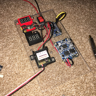
Next up was test fitting all the components on the perspex board.
Just waiting on the M2 thread fittings.....
I started routing and soldering the wiring next. I drilled holes to route the power wires behind the panel and to help identify the voltage, used yellow as positive for the Audio FX sound board as it uses a lower voltage than the amplifier.
The M2 inserts and bolts/screws arrived in a few days via eBay and where inserted into the rear of the board.
October 2020.....update
Got on with refitting the sound system. The extra perspex material has now been removed and a suitable location to mount it has been prioritised. A wood spacer block is needed to raise off the vertical frame support to allow the wires to fit behind. This new location is closer also to the 12v terminal distribution block.
I also fitted some of the new cable clamps I designed and 3D printed.
June 30, 2020
Thingiverse - digital volt meter holders now online
June 29, 2020
Thingiverse Page - James_R5-D4 = latest designs.
Update: 22.6.2020
The volume control box holder, needed to be slightly modified. I should of made the cable hole larger as the two struggled to go through. So had to trim off the upper section. Not the end of the world as the idea was to fit a lid. Also the hole for the rotary had to be opened up a bit, printer tolerance. The best bit tho was the fitting of the thread inserts.
Volume control knob, needed only its shaft hole to be opened up. I wanted it to be a tight fit, but was a little to tight at first.
Utility arm bracket, these printed great, but still they need redesigning as I just can't get the flat parts to fit the curved angle of the arm. So back to the drawing board for these.....
Next up:
The Digital Voltage units. I didn't have one to hand when I was drawing up this model for another project, so missed a few details. Both are not major things and one was easily solved by trimming the fixing tabs off the digital meter.
Once tabs removed and rear circuit board filed down a bit, the digital push fits in. The upper recessed tab I had originally intended to have printed labels stuck in stating the voltage. On hind sight though this is a bit pointless as you'd visually see the display.
Lastly, the mini voltage regulator needed a new holder.
The regulator clips into the holder and is a snug fit. I need to add a securing holed tab.
When I'm happy with these, they will go up on my Thingerverse page.
November 22, 2017
R4-D4 Dome work progress 2.5
Once home, I removed the raft & supports. There wasn't much cleaning up needed.
Later I then test fitted the components & whilst I had some free time, connected up what I could.
It may look complicated, but I don't do complicated lol, all 'plug-n-play' here.....with a bit of splicing of the digital volt meter to be soldered to the output pin connectors of the voltage regulator unit. The bottom two red wires are to the momentary switch I used for testing. This you can see in the picture below.
November 21, 2017
R4-D4 Dome work progress 2.3
Panel 5 received a PVA wash, rasp work to take off the edges and sanding with paper (repeat until smooth). Wood filler was then applied, then once dried, this was sanded smooth.
Then it was onto the last curved panel. Trimmed it to fit along its edges (the clamped edge), then glued and clamped into place. First side.
Once dried, I glued the second edge down and then trimmed off the excess along the bottom edge. Then it was back onto rasp file work, and sanding smooth.
Friday I glued up the first edge of curved panel no6, I took the dome home and at the weekend I was able to finish glueing the second edge. Then a PVA wash and some wood filler, ready for work on Monday.
After sanding the filler and wood smooth, I gave the whole dome a spray with primer/filler.
Then on the lunchtime, I gave the whole dome a smooth sanding.
This process helps pickup areas that need small amounts of wood filler.
I also started on making the lid.
April 27, 2017
Control Panel upgrade 1.0 (2017)
With the new addition of the SyRen10 dome speed controller, I wanted the main control panel to be self contained. As I originally (due to time/space) had the 24v to 12v converter mounted on the sound board.
I wanted it tho to be independent, so with the panel out of R5's body, I got to work on re-working the layout to fit it all on.
So connectors came, heat shrink, cables & terminal block too. Any free time I spent on cutting, soldering (all connectors, non of this crimped stuff going on here!) then heat shrinking everything in sight lol.
Found a double sided sticky pad, for the transmitters receiver, to mount it on the panel.
March 13, 2017
R5's dome rotation upgrade 1.1
So that put a stop to that idea lol.
Next was to simply buy a thinner piece of hardboard and it plus the 10mm thick bearing would equal the right height again.
Whilst I was doing all this thinking/planning, I started to remove the old lazy susan & electrics that wouldn't be needed.
This was a great idea for a cheap and easy way to control R5's dome rotation, and has served me well. But it's replacement will same on space and all this wiring!
I also uninstalled my old & original, RC transmitters receiver unit. I had kept in, just incase I needed to swap it back over, but it wasn't necessary. It was replaced by a screen used version from a fellow club member, much thanks go to Colin Barker for his generous gift.
Sunday was when I was able to get on with some REAL work.....
April 13, 2015
R5-D4's Sound system installation - UPDATE
March 29, 2015
R5-D4's Sound system - Audio FX & 12 Channel remote.
With all the soldering going on, I didn't like the look of the work I had done on the Audio FX sound board. So as it came with pin's, I ordered some female crimp connectors off eBay to crimp & solder the wires to these. These were then covered in heat shrink.
At last my 12 channel remote control unit came :)
March 16, 2015
Dome electrics - power connection
.......ordered another servo......fingers crossed!
September 10, 2014
Electrical: Batteries arrive & more installation 1:4
Monday, my.....sorry, R5's Batteries arrived. They tried to deliver them last Friday, now that's quick service!!
I placed them into the base area and they look good! :-)
I then started looking at how/what I had material wise to clamp them in place. Something lightweight, but strong! Found it! A strip of U section Aluminium (not shown in picture). I had left over. So after marking it up, into work it went and had two sections milled out. These help with securing the batteries and stabilising them from possibly sliding around. Next was to make up two angle securing brackets for the ends of the strip to be bolted onto.
Last night (Tuesday) was a good work night!!