Showing posts with label upper utility arm socket screen. Show all posts

May 04, 2022

Happy to help fellow builders: ROJO CINCO DROIDS

The other month, I got asked about my utility arm rear screens and if I could share the stl files.

Below is the results.....


Checkout Ricardo's awesome Droid builds over on his website:


April 12, 2021

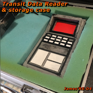
Transit Data Reader - for R5-D4's Utility Arm Socket screen (Part 2)


Installation of the electronics.

I had to print off a small housing for the original electronics panel that required to be re-positioned outside of it's battery box, so that the button could be pressed. This also required the battery terminals to be de-soldered from the board and wires attached to make the compartment separate.

This picture shows the lite panel, before I sprayed up the box.

I've added a coiled cable from an old mobile phone car charger lol. This then connects to the 'plug socket' end with the magnets fitted.

I added some clips to the inside of the bottom opening, for the hatch lid to sit on (one thing I had forgotten to do on the original design).

I've been thinking about what colour to paint the 'plug socket'. First I sprayed a black and grey combo to match the box, then went with black and silver [for the connection interface].

I needed a carry/protection case, found an old RC Transmitter box. Fitted it with foam I had leftover from a past project, and trimmed it to fit inside the case.


March 17, 2021

Transit Data Reader - for R5-D4's Utility Arm Socket screen (Part 1)


This is a similar design based on this image (below), taken from the Solo 'Official Guide' book. I thought this would be a good idea to have to connect up with R5’s utility arm socket and use it as a data transfer terminal. Similar to those seen in the original Star Wars scene to download the plans for the Death Star & then similarly to when R2 downloaded the data in The Rise of Skywalker.

To keep things inline with the retro feel, I found some coiled cable from an old car mobile phone charger, that can be connected up to the reader and the plug.

The design was originally sectioned up into a upper and lower section, but I decided to print this as a hollow one piece. There is a ‘hatch’ in the bottom to allow access inside. This kinda helped getting the supports out, but for future printing, the sectioned version would be the way to go! This took over a day to print lol.

The next job was removing the internal support :(
I hate wasting time & material!!

Next up though was sanding the unit & a coat of filler primer.

Once dried, a test fit of the EL panel. Which needed some slight filing of the hole to allow the plug to fit through.
Cut a piece of opaque plastic as a cover screen. This will get marked up later or a second screen will, fitted underneath it.


A coat of black matt paint was applied and allowed to dry. Later I then masked off to allow the front button panel to be sprayed white.
I didn’t have a grey paint, so thought I’d try the silver. But this was TO silvery for my liking. No amount of buffing and over spraying with black was going to dull or improve the appearance lol. So once sanded back, another coat of matt black was applied all over.

I made a stop at a ‘Halfords’ on return from school run and picked up (hopefully) a more suitable grey colour.

I’ll then masked off the lower part to remain black and give this a spray.
Much happier now with this look.... next up was applying colour to the recess and buttons. Using a thin brush, I sprayed black paint into a lid and brushed it onto the recess & also dry brushed the grey paint too. I then swapped over to the white for the three main buttons.

And here is the finished painted Data Reader:

Compared next to the original design.
~~~~~~~~~~~~

On the plus side, this has given me time to update this with a better, more open bottom hatch, fixing screw holes for brass threaded fittings, meaning that this can be printed in three parts, less support material = quicker print time.....

.....I’ve just ordered some more filament :D so no doubt a second print is on the cards....or should that be print bed :D

February 23, 2021

Utility arm UPPER socket screen (Part 4)

 Can’t believe it’s been two months since I fitted the upper utility arm socket screen!

In my attempt to finish off unfinished parts, I got on with weathering it. So far I have just added matt black , but like the lower one, I will add burnt umber & ochre yellow to give it that Tatooine sandy feel.
Utility arm socket screen

December 16, 2020

Utility arm UPPER socket screen (Part 3)

 Test fitting of the panel identified that a few things needed tweaking.

Utility arm socket screen installation

  • The utility arm wouldn’t close properly.
  • The screen was still a bit tight.
So firstly, the utility arm was not closing properly. This I found was down to the pivot pin not having enough clearance below it. It was being restricted by the lower frame panel. Before fitting the socket screens, there was a bit more space. As the pivot pin had left a rub mark on the new paint, I could see where to make a recess with a 10mm diameter drill bit.

Utility arm socket screen installation


Next was the socket screen itself. I had to clean off over spray paint from the top and bottom faces & trim a bit more off the pivot arm end. This was stopping the screen from going back far enough, which was restricting the utility arm from closing fully.

Really pleased with how this is looking. Just need to weather the screen and finally fit it in place.

December 15, 2020

Utility arm UPPER socket screen (Part 2)

Top utility arm socket screen test fitting

Before spaying up the screen white & then getting to work on weathering it.....see below.

The piece of wood that sits between the two utility arms, needed to be thinned down for the screen to fit. My original measurement was for a snug fit, but the print was just a bit higher than expected, so rather than take a blade to the 3D screen print (loosing details) I decided to trim the wood piece. This then needed some wood filler before repainting. It was black and I did respray it matt black again, but am thinking white so it all blends together.....

Utility arm socket screen.

Filler primer added

Top white coat drying off.

Once all dryer I’ll start weathering this piece and the screen before re-installing.

December 11, 2020

Utility arm UPPER socket screen


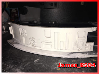
As mentioned in previous post, I needed an upper utility arm socket screen. I CAD reversed the 3D files and had to do some height changes, as due to my wood build, the dividing shelf between the two utility arms & the Large Data Port, mean less height than the lower section.

I made a design change to remove the opening for the Trading Card Dispenser, and some other alterations so it differed from the lower screen.

Started the print Sunday afternoon around 3pm (UK time), layer height of 0.4, and it eventually finished Monday morning 9am (UK) lol. 17hrs 39mins.

Forgot supports

I had supports on but only touching build plate.... I think?? So apart from one ‘not seen area’ the print came out great!

First few layers

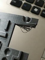
Not sure if bed or extrusion needs adjusting as I get this on the first few layers of the print. Nothing a knife can’t sort but still lol. It was extrusion, wasn’t hot enough for the initial layers.

After cleaning up work, it was time for primer/filler painting. Once dried, a bit more cleaning up before top coat.