Droid Builder

Extra Projects & Event Page's
- Home
- Trading Card Dispenser (NEW version 3) - TCD [2020/2022]
- Trading Cards
- R5-D4's ....Bad Motivator development
- R5-D4 - silver neck details
- R4-D4 - Dome [wood build]
- R0-D4 Dome [wood build]
- 3D Printing
- *** Star Wars Shoes ***
- GOUD-4 Messenger Droid - Solo ASWS
- Event: Mshed Bristol 2025
- Event: Mshed Bristol 2024
- Event's 2018
- Event's 2017
- Event 2016 - "Celebration Europe"
- Event's 2015
- Event 2014 - Chippenham Sci-Fi
- R5-D4 - events page - The beginning (2013)
- ** R5-D4 patch **
- R5-D4 Photos
- Costume for my Son - Han Solo -
- Costume for my Son - Boba Fett
- Droid Caller - Han Solo style
- Scanning Crew Container - Transmitter Storage Box
- Stormtrooper - me
- Rogue One - trading card storage box
- Rogue One
- Jabba’s gate prop for Celebration 2023
- Treadwell Droid - WED-15-77
July 24, 2024
Instagram post: QR codes
November 26, 2022
Treadwell WED-15 droid build : Part 5 - 3D printing lenses
September 18, 2022
Wedding Ring Utility unit...... (box)
February 23, 2021
Utility arm UPPER socket screen (Part 4)
December 16, 2020
Utility arm UPPER socket screen (Part 3)
Test fitting of the panel identified that a few things needed tweaking.
- The utility arm wouldn’t close properly.
- The screen was still a bit tight.
December 15, 2020
Utility arm UPPER socket screen (Part 2)
Before spaying up the screen white & then getting to work on weathering it.....see below.
The piece of wood that sits between the two utility arms, needed to be thinned down for the screen to fit. My original measurement was for a snug fit, but the print was just a bit higher than expected, so rather than take a blade to the 3D screen print (loosing details) I decided to trim the wood piece. This then needed some wood filler before repainting. It was black and I did respray it matt black again, but am thinking white so it all blends together.....
Once all dryer I’ll start weathering this piece and the screen before re-installing.
December 13, 2020
James’ R5-D4 YouTube channel 2020
Had this congratulations email today from YouTube for all my videos uploaded in 2020 lol......all 12 minutes of them :D . Not exactly ground breaking mind you, and a few million off any YouTube awards lol, but I appreciate everyone who has watched etc and I hope they have been entertaining or educational.
See screenshots below.... then head on over to my channel to contribute to the ‘ups’ & likes and shares, thanks everyone.
My YouTube channel link below:
December 11, 2020
Utility arm UPPER socket screen
I made a design change to remove the opening for the Trading Card Dispenser, and some other alterations so it differed from the lower screen.
Started the print Sunday afternoon around 3pm (UK time), layer height of 0.4, and it eventually finished Monday morning 9am (UK) lol. 17hrs 39mins.
I had supports on but only touching build plate.... I think?? So apart from one ‘not seen area’ the print came out great!
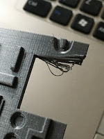
Not sure if bed or extrusion needs adjusting as I get this on the first few layers of the print. Nothing a knife can’t sort but still lol. It was extrusion, wasn’t hot enough for the initial layers.
After cleaning up work, it was time for primer/filler painting. Once dried, a bit more cleaning up before top coat.
December 05, 2020
‘Trading Card Dispenser’ utility arm inside panel 1.4
The rear utility socket screen is 99% complete. Finished off painting it today and fitted (glued) the rear piece in place (not in the picture below).
Next up was re-fitting this into R5’s utility socket......see below picture.
Need to do a panel now for the top socket.
November 30, 2020
‘Trading Card Dispenser’ utility arm inside panel 1.3
This was the next item that needed spraying up.
November 28, 2020
‘Trading Card Dispenser’ utility arm inside panel 1.2
So whilst designing the rear screen for the TCD, ‘Trading Card Dispenser’, utility socket area. One thing came to me & that was the shape of the ‘hand/grip’ of the arm. I made a recess that matched it in the screen. The idea being that when opened anyone viewing inside would see it and think it was like this for a reason. This was part of the second design lol.
The third and final design, I had an idea. Rather than just have a recess there, make it into an actual ‘thing’. Thinking about events etc and when the droids are just parked up, how about making a power charging/data transfer plug. So I measured up depth, plus other dimensions and got designing.
I remembered I had some magnets that would help hold the plug in place. These magnets are fitted with wire for upto 8amps, not that I’ll be going there lol (Heat shrink was added to the fly leads). But it meant that I could wire up an LED to illuminate when the magnets made contact with them the plug.
I printed the plug in two halves to ensure good surface finish all over. I designed and printed an end cap that I would connect up to a fake power/data tube.November 22, 2020
‘Trading Card Dispenser’ utility arm inside panel 1.1
Progress, after a few design changes (as mentioned in post: 1.0) I finished it and printed the screen on the Tevo at home. 0.15 layer height and took hours to print!
Above pic shows print with support still in place.
After cleaning it up, test fitting showed that I still needed to make some adjustments to get it to fit. Also, there were some areas that protruded to far out and these prevented the utility arm from fully closing. These parts were cut away and I’ll update the CAD file to match.
I’ve also been working on a something extra, just as a bit of fun which will be incorporated into the utility arm recess.
November 19, 2020
Utility arm - servo installation update 1.1
November 9th 2020
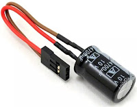
One thing with servos that has bugged me since starting to use them with R5's build, is the twitching that sometimes happens. So I did a search for the cause of this and found loads of, mostly old, YouTube video's referencing 'Glitch Busters'.
So after having a search online and ultimately looking on eBay lol, I decided I'd have a go at making one myself. Capacitors ordered and I already have the connectors.
Connected up a capacitor and plugged it into the system......no noticeable difference, but I'll leave it in just in case lol :D
November 16th 2020
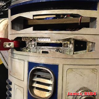
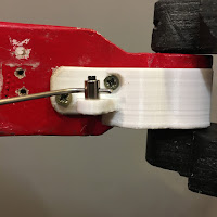
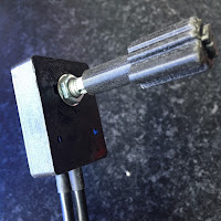
Worked on the servo fitment. Cut the four screw threads down to correct length needed. Also opened up the upper axle hole in the wood, to allow the utility arm to move more freely. I fitted the white 3D printed bracket, which I screwed into position, but the thickness of the base, pushed the utility arm up and it rubbed then on the skin opening.
................So I removed this part of the bracket
I had test printed off a new 3D piece of the screen which would allow the servo linkage to pass through it.
This piece would require a bit more alteration as I had not left space for the bracket, once in the closed position.
Next design change is to give a bit more space top/bottom of opening and to fill in the original smaller opening, seen in above picture. You can see I also tested out fitting springs to the servo arm.
Final design of the one piece screen has been drawn up and will be printed shortly. Hopefully I've got everything right lol.
November 04, 2020
Utility arm - servo installation update 1.0
Now to sort out the utility arm activation, allowing the TCD to dispense cards.
Dug out all servo box again and re-using what I already had, located a position for the servo to be installed.
November 02, 2020
‘Trading Card Dispenser’ utility arm inside panel 1.0
Since installing the bracket that holds the TCD, ‘Trading Card Dispenser’, the idea of making/replacing the rear metal screen with something more fitting has been something I’ve been working on.
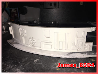
I upgraded the original piece to have a curved front and increased the thickness to act as a stop for the utility arm when it’s closed. I need to recess some details a bit more on one side.
Next up was the sides and top. I drew up these in autocad inventor, longer than needed, and 3D printed one side off. Took this piece home and got to measuring and trimming it to fit around the utility arms pivot point bracket. See above picture.
As my droid is custom built, using the plans is only a guide lol.
After designing up a full screen, to save printing time I only printed the new part, seen in red, as it was a Friday afternoon and wanted to take it home to work on over the weekend.
The above picture shows the two pieces, which will eventually be printed/printable as one. I need to ad more rear fixing points as R5’s frame is wood.
The recesses in the red part are for future greeblies to be fitted. But rather than them being curved, I’ll make them flat so that the inserts can be printed in a flat orientation for better print results.
There is also a need for a hole to allow the servo arm to pass through to activate the utility arm. But one step at a time lol. I will of course upload this to my Thingiverse page.
June 29, 2020
Thingiverse Page - James_R5-D4 = latest designs.
Update: 22.6.2020
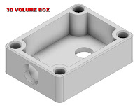
The volume control box holder, needed to be slightly modified. I should of made the cable hole larger as the two struggled to go through. So had to trim off the upper section. Not the end of the world as the idea was to fit a lid. Also the hole for the rotary had to be opened up a bit, printer tolerance. The best bit tho was the fitting of the thread inserts.
Volume control knob, needed only its shaft hole to be opened up. I wanted it to be a tight fit, but was a little to tight at first.
Utility arm bracket, these printed great, but still they need redesigning as I just can't get the flat parts to fit the curved angle of the arm. So back to the drawing board for these.....
Next up:
The Digital Voltage units. I didn't have one to hand when I was drawing up this model for another project, so missed a few details. Both are not major things and one was easily solved by trimming the fixing tabs off the digital meter.
Once tabs removed and rear circuit board filed down a bit, the digital push fits in. The upper recessed tab I had originally intended to have printed labels stuck in stating the voltage. On hind sight though this is a bit pointless as you'd visually see the display.
Lastly, the mini voltage regulator needed a new holder.
The regulator clips into the holder and is a snug fit. I need to add a securing holed tab.
When I'm happy with these, they will go up on my Thingerverse page.


