Showing posts with label Audio FX Sound Board - WAV/OGG Trigger with 2MB Flash. Show all posts

October 17, 2024

Treadwell WED-15-77: Part 28


July 2024:
Here was to be the final instalment of the Treadwell build 😀
Recent work has been mostly focused on making the sledge to transport WED on, via the cars roof rack.

Sounds:
Needed to fit a speaker and wasn’t happy with my original position idea. So decided to fit in inside the ‘logic housing’.

Position located:

How to find the centre of a circle lol

Dug out this adjustable hole cutter. Think I last used this to make the holes in R5’s legs!

Making a start on the hole.

One hole cut out.

Speaker fitted with its spacer ring, that I had previously made for the GOID-4 messenger Droid.

Re-installed the ‘Logic housing’ (the hole cutter wouldn’t fit inside it).

I had added longer leads from it to reach the amplifier board.
Just need to finish off some connections and save some sound files. Keep forgetting these last two pieces. Needed to buy a proper servo controlled switch, similar to the one used in R5, but this ones a single and much smaller.
Another tweak, was the addition of a volume (potentiometer) to boost the sound. When I couldn’t hear it at Mshed event, I knew I had to install one.
3D printed the knob from a file on the Prusa printables website.

Had to rewire the signal to volume dial to amp to speaker wires.

Claw arm servo:
The new micro servo arrived sooner than expected lol, but I had already started on a modified 3D printable housing to fit a new metal geared SG90 size servo. It didn’t take up much more space , but i had to reposition the securing screw, and add a second one.

I used brass knurled threaded inserts & M3 screws.

I made a slot in the side to allow the servo horn some freedom. This once finished, could be covered.

I needed to add a slot in the claws tube to allow some flexibility for the wire that connects to the servo horn.

I also added a location hole for a screw.

Next was to remove the servo plug so that it could connect with the servo lead.

Almost forgot about painting it…..
Primer applied after some sanding.

Weathering:
Dug out the paints and got to adding brown, yellow and ochre.

Then black to give the dirty oily look.
At the Mshed event, I was asked by some of the builders if Tread was metal construction, they were surprised to hear the upper section was all 3D printing.

Upgrades:
I know I said this was going to be the last post on this build, but I have a few more tweeks to do with things I wasn’t happy with, so there’s more to come.


July 25th…….
Wheels:
The original wheels were spaced away from the base, as can be seen in these two  photo.

original deleted scene SW ANH
remade version for the prequals
    

So I decided to draw up some spacers and 3D printed them. This along with some more substantial axle bushes with bearings in, to better support and properly align the wheels. And finally, some new axle's at over 180mm in length!

October 26, 2020

Sounds for Droid 2020 - 1.8 installation

Made up a new bracket for holding one speaker, out of some MDF wood. The prev one was perspex and was attached to the old sound board.

new speaker position

I may mount the second speakers in a rear position.

Continuing on with organising the wires, the slip ring underside wires are always annoyed me as they are stiffer due to less strands. This makes it awkward reaching inside as they get in the way. So I decided to cut them short and connect new, more flexible cable. This will also be yellow to match up with identification of the voltages, yellow being 12v positive.

slip ring cable modification

Next up was to install the sound board. I changed my mind about which side to mount it on. Decided that it would be better over on the right hand side. I needed a spacer block, so cut a small piece of wood, marked the boards fixing hole position on it, then drilled clearance holes and screwed the spacer block to the frame.

spacer block

Next up was to then mount the sound board to the spacer block.

Sound board fitted to spacer block

I de-soldered the red power cable on the sound board and replaced it with a yellow one. I had some yellow heat shrink to cover the red wire for the Trading Card Dispenser electronics box.

Next up then is to connect the speaker, route the servo lead which operates the relay switch and test out the amp/speaker. Also need to look at where best to fit the volume control knob.

October 15, 2020

Sounds for droid 2020 - 1.7 Sound board build

Back in August 2020   

 After lots of design layout ideas, and 3D printing a special holder for the sound components. I decided to just go back to basics and use Perspex.....as I had found some spare. I still utilised the digital voltage meter holders & also the Dual Relay Switch holder, as these don't have there own fixing points.

I dug out all the old nuts and bolts previously used and thought.....naaaa, I don't like the look of them. So I drilled a hole and test fitted a threaded Brass insert. It worked! So positioned the components, marked and drilled holes......all except the sound board (as this requires M2 size thread fittings) and then using my soldering iron tip, melted into place the Brass inserts.

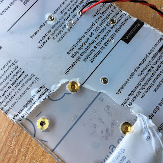
Thread inserts added to Perspex board

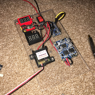
Next up was test fitting all the components on the perspex board.

Sound Components going onto the board

Just waiting on the M2 thread fittings.....

I started routing and soldering the wiring next. I drilled holes to route the power wires behind the panel and to help identify the voltage, used yellow as positive for the Audio FX sound board as it uses a lower voltage than the amplifier.

The M2 inserts and bolts/screws arrived in a few days via eBay and where inserted into the rear of the board.


October 2020.....update

Got on with refitting the sound system. The extra perspex material has now been removed and a suitable location to mount it has been prioritised. A wood spacer block is needed to raise off the vertical frame support to allow the wires to fit behind. This new location is closer also to the 12v terminal distribution block.

I also fitted some of the new cable clamps I designed and 3D printed.

new [yellow] cable clamps installed    new [yellow] cable clamps installed
The board just needs terminals for the 12v power.

sound board ready for installation


March 30, 2020

Sound board enclosure - Prusa [was Thingiverse] Page

After posting up my 3D drawing for the new Adafruit sound board enclosure, I had questions so.... I found my old sound board, and was able to simply extend the design to a length suitable for it. I needed to add in a recess opening for the phono jack socket.

I've uploaded the stl file to my Prusa page, (was Thingiverse) but as I'm not able to print off and test, as usual, due to working from home in this COVID-19 situation, the file is deemed a Work In Progress. If you do download to print it and find any issues, please let me know so I can update the file to better fit.
Adafruit sound board enclouser

Adafruit sound board, enclouserAdafruit sound board, enclouser
The above pictures show the designed enclosure, the sound board its designed to be used with and the final picture is my original sound board that broke, due to the plug bending and braking the socket off the board.

May 13, 2019

12 Channel remote - upgrade.....New replacement Relays

Well the testing of the new 12 channel board didn't go well. A voltage regulator setting may have damaged one of the boards components, but worse, the sound board is now also unresponsive.
'digial' 12 channel remote?

On checking the sound board, by plugging it into a PC, it should appear as a 'folder' like a USB drive would. But although the board lights up, the board does not show up as a folder options.....?


~~~~~~~~~~~~~~
So back to work on the original 12 channel board.
I had ordered some replacement relays....before I remembered that I had another damaged one. Nevermind, at least I'd know that I would be working with (hopefully) working relays and not damaged ones. As I've said before, I'm not an electronics person, but mechanical, so checking the relays & replacing them to check, is my first part of this process. A co-worker who has got into electronics WAS able to test an old relay v a new one and found the old one to be faulty. So things are looking up for this little upgrade.
replacement relay units
These were 5 for £2.55 off eBay.

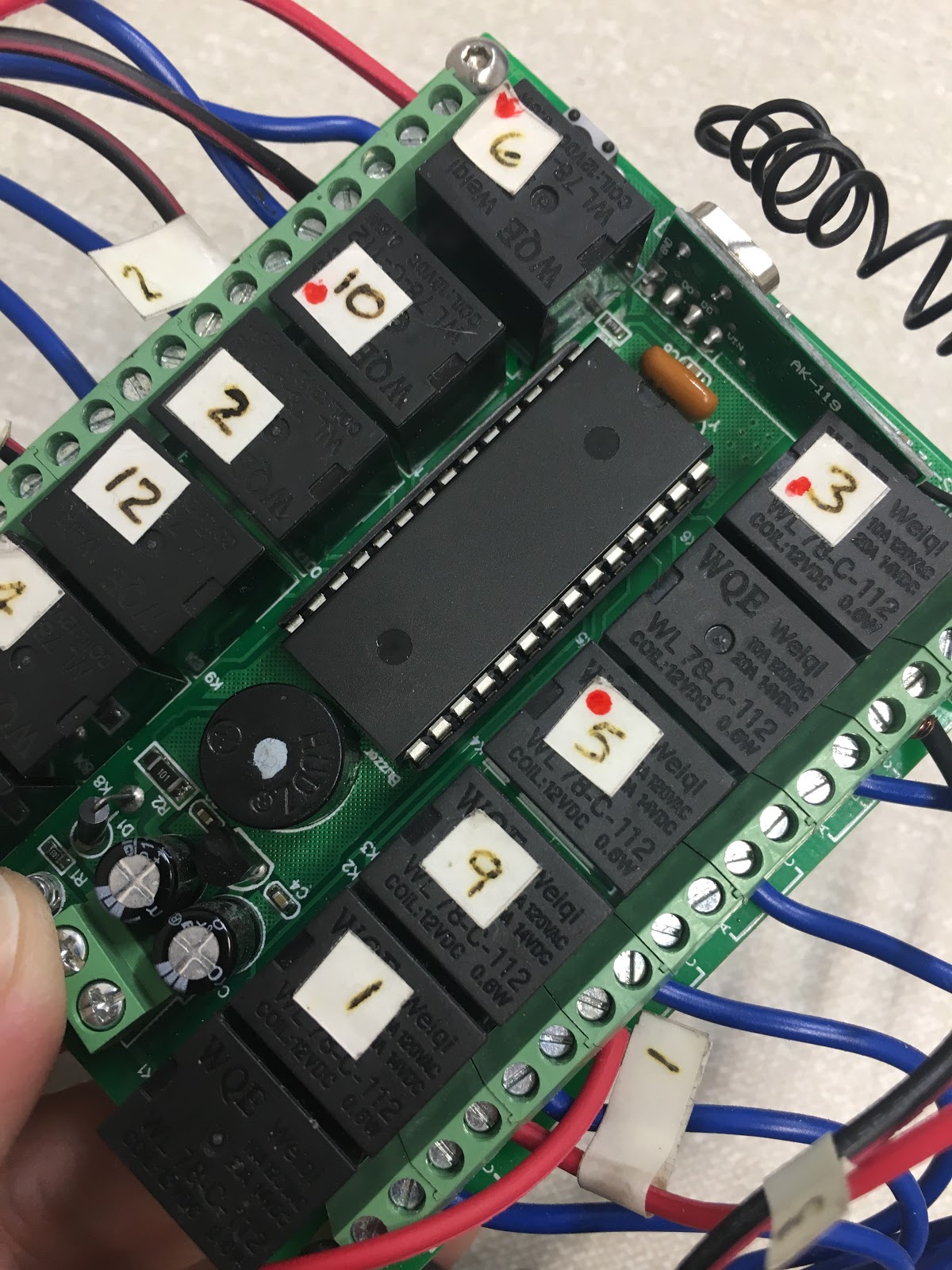
Next up was to mark the relays, with a red dot, that didn't respond to the control.
replacement relay units
De-soldering these joints was fun lol. Quickly heating up the pins to be able to leaver them up out of the holes.
replacement relay units
First relay removed. I was going to go and solder in the new relay, but thought it would just be easier to remove all the 'faulty' relays first. Which is what I did.

Once I had cleaned up the holes, it was then re-soldering in the replacement relays.

And then, once all back in.....the test..............FAILED.....

Relays were carfully soldered back in place. But they still wouldn't switch when remote was activated. Checked resistance with a multimeter and they are not latching when power goes through them, but give a reading when power is not.

Looking like I should cut my losses and buy a new 12 channel unit.

June 11, 2018

R5's sound system - maintenance work

I was never happy with the 12 Channel remote controller as it's relays were ALL over the place, not as you'd expect, fitted to the board 1, 2, 3, 4, 5 etc. Plus the fact that some of the relays don't even work!!

Sometimes some of the sounds don't play either, even tho they do when on the test bench.

One sound that didn't work was the Bad Motivator 'pop-bang' effect. This I noticed when at MCM London the other week.

So I pulled out the board and give it an inspection/maintenance once over. This is where I found one of the wires had actually broken.....The Motivator 'pop-bang' sound effect.

With the actual motivator only recently re-fitted, I didn't realise it was down to this break.

So a quick re-wire and all's now working again.

Future Upgrade: I keep looking at replacing the large board with a smaller 'digital' version of the 12 Channel unit. It has no relays, just a chip!
Digital chip version

12 channel 's still
Mentioned this to Simon B recently at MCM London, as he also had problems with the relay version. This 'chip' version is on my list of upgrades to try out!

October 24, 2016

R5-D4's Adafruits FX sound board issues....

The weekend, I eventually got round to looking at R5's sound board 'issues'. R5's 'sad' sound on remote switch no.3 wasn't working or worked intermittently. With the board out and on my desk, I thought I found that the wire was the issue. Strange tho as it is no different to the other wires, all fitted at the same time. I trimmed the end of the wire and refitted it. It's still intermittent, so will make up a new connector wire, but for now it's working, will see how it goes.

Next on my list was the theme sound that has never worked. It's file size was always in question, even tho the Adafruit runs on .wav files (not MP3's). But after playing around with the size and it still not working, I tried it on another switch.......and it works! Placed a sound file on the T04 file.....and it didn't work??

adafruits FX sound board
(old ref picture of original wiring up)
So I moved the other sound to a 'T0_NEXT' location on the board. So lost one more button, which didn't have any sound, but now gained another, a short SW Theme into lol.

October 23, 2015

Sounds .....like...?

19.10.15
Another half hour playing with the sound board and 12 Channel remote.
Few more 'random' settings for sounds and a clip of the Star Wars theme.

Just now need to re-label the remote and back in business, one less thing to do to be ready for Chippenham Sci-Fi Day on the 24th.....

22.10.15
So last night I eventually finished installing servo no2 for the lower utility arm & was going through everything and checking the sounds.....

.......and no SW theme played? :(

Will have to see what happens tomorrow, and then look at it next week.

October 09, 2015

You know that new 12 channel remote I said I wouldn't be needing.....

........well, Wednesday night when I was having problems with R5's motivator actuator not popping up [see next Blog update]. Well I somehow managed to kill the 12 channel remote board :(. It beeps to receive the remote's signal, but nothing else works.....

So out came the replacement one and wired it up. But things are never that simple. The relays are not in order and two don't work at all??
R5D4

But I've multiple sounds via the other button's so not the end of the world.

I then labelled up the remote, so I know what sound is which. Thought it might come in handy if he's talking to kids :)
R5D4

Roll on Saturday :)

October 07, 2015

Electronics & Automation upgrade time..... 1.1

Servo's &  brackets & leads arrived at the weekend.

The servo's I'd ordered were cheap budget Tower Pro ones. Only because I wanted to test that I could get the transmitter to work them. I'd also bout some brackets to be able to fit them. These didn't fit over the servo's location lugs, so I had to file them down a bit to fit. No big problem and they now fit a lot better.

So got to playing with the Transmitter settings in the hope I can actually control the Utility arm's once connected up. See next update on Utility Arm movement Blog post.....

Result!

Thought I'd have to have both arms servo's running off a Y-splitter, but I must of set both 'switches' A & B the same, and the knobs too. This means I can dial the servo's to OPEN position, and then flip the switch and the action is cancelled and the arms will 'CLOSE'..... well, that's the thinking, tho may need to swap this round.

LED's & Fibre optic cable came too. More on this later on......

On order was a new 12 Channel remote control, for sound activation........hope this one works properly!

.......well, this came a LOT sooner than I expected, minus a mini battery [no big deal].... But it arrived the day after I actually got my old one working properly!?!?!

Thought I'd try to sort old 12 Channel remote, one last time. Noticed that the remote's LED was dimming, so swapped it over....... All the channels relays 'switch', they all work and they all play their connected sounds.....What the.....?!?!? Am not 100% sure that this was the cause of the problem, but can't believe that this could of been the whole problem?
But I don't really care, am to happy that it all works lol, even the 'NEXT' function settings work, so I have multipule sounds from clicking one button!

Wired up one of the leads from the slip ring to activate R5's bad motivator sound from the second remote, but couldn't get it to work. Not going to worry to much as it will just have to be operated from the main remote control and be a two finger button pressing operation lol

September 23, 2015

Electronics & Automation upgrade time..... 1.0

As I was not happy with the limited sounds available, due to the 12 channel remote unit not working properly, I've now got round to it & ordered a new one, should be here next month lol.

I've also ordered some servo's to see about getting his utility arms moving. Also ordered a y-lead splitter in case I need it.

June 26, 2015

'Bad Motivator' - upgrade to power lift 'Blown' status 1.4

OK, so I got round to planning how to operate R5's pop-up motivator and also to trigger the smoke system.
  • activate motivator to pop-up
  • activate sound of blown motivator via the Adafruit Audio FX board
  • activate smoke system.
I want the three things to work at once from one button. Originally my idea was to use the 12 channel remote unit I had for R5's sounds, but the one I have/had was faulty and so I gave it a .......'vote of no confidence'......lol.

As I'm still working on a budget, I searched eBay for suitable (& cheap) components. If they work, great, if they don't then the price goes up.

Found a four button remote control unit, and a timer switch relay unit.
R5D4, Bad Motivator

R5D4, Bad Motivator
The remote & the switch timer relay only cost £8 each.

April 23, 2015

R5D4 - video of his limited sounds

Quick video of the limited sounds available to R5
.....well.....he doesn't say much in the film anyway lol


Just click on the pic to take you to R5's YouTube page

R5D4 - prep'ed ready for transportation

Spent two hours re-installing all of R5's electrical boards, sound system board and then testing it all.

This was the first time he was all together, dome on, lights on, sound on!
R5D4, R5-D4, r5d4, r5-d4

The sound system was loud! Which is a good thing as you forget that when testing in your garage or at home, (though not at half past 12 at night! lol). You normally DON'T have any loud background noise. But at event's, this increases dramatically. So to be on the safe side, I tested the amp on full power by flipping the two dip switches.......now THAT's LOUD!!! :D
R5-D4

April 22, 2015

Sound problems - 12 channel remote....

Where to start......

......this Build Blog is about the up's and down's, and here's a down post.....

Well, I'd missed crimping an earth connection lead in the eyelet socket, so that explained why one channel didn't play. So redid the wiring into a new eyelet, only to find it wasn't the right size hole (a rouge size). So had to re-do .........again, third time lucky?
12 channel remote
Before I found the missing earth crimp.
Then, all this time testing for sound and not getting anywhere fast, only to find that the remote channel I thought was no1, was in fact no7, (these come with no instructions mind). Am still having issues with actually setting up the remote, as one minute it works (you can hear the relays click) and plays when buttons are pressed, the next some don't??

Another 3 hrs of waisted effort last night, out of the 12 channels, I have 4 channels that will play sound, because the relays or the remote/board programme? And 2 channels that are for some reason repeats of two of the 4 channels?? And there not even connected up???

Conclusion:

  • Either the 12 channel board is faulty.
  • My soldering defo needs improving [this goes without saying lol]
  • There's a problem with the Audio FX board [not likely as test triggers all the sounds]

April 16, 2015

Sound board - installation complete 1.1

Made up some wood location stands, cut slot's into them and screwed them to some MDF base plates. These were then screwed into place.

I then made up a cardboard template of the metal bracket I wanted to make to secure the top of the board. Cut, drilled and then bent into shape, marked position on board and drilled a clearance hole for a bolt, washers, spring washer and a butterfly nut, to secure in place.

I then finished off some more wire's, soldering and connected these back up to there respective terminal blocks.
R5-D4,

R5-D4

R5-D4 sound system
The top securing bracket can be seen better in this image.
This lot took over an hour to complete!