February 2023:
More building work from Mike & he has excelled himself!!
He’d finished building the side unit and on Friday 17th, I went up to help him and his brother Mark, assemble the door.
There are three units that are bolted and screwed together to lock everything in place. When I arrived the base was already outside Mike’s place.
Next was bolting the support legs into place.
Then the upper support batons, that support the upper door unit. Mark & myself then lifted the upper section into place whilst Mike secured the batons to the rear.
We then carried out the lightest piece, the end wall. This gets bolted and screwed onto the other two units, making a rigid corner structure.
Mike brought out one of his droids and placed in front for scale and some more photos.This was when the passing public started putting two and two together lol.
With the build almost completed, it’s just left for me to finish the TT-8Y droid. Mike has made the door flap panel to open up.
I have also made a start on writing up assembly instructions. This display will be handed over to the R2 Builders Club, for further events, so instructions for putting this together will be needed so anyone can do it.
TT-8Y droid progress:
The model components were designed to be static, but I required it to operate opening of the eye lid. So I had to do some thinking. One of the stl’s I didn’t print out as it wasn’t necessary and would of added to the weight. So I had to draw up some pivot point rings to allow the upper eye lid to be able to move.
Here you can see them on the lower fixed eye lid:
I had picked up some spray paint that I had used before and liked the colour of. With it i made a start on the pieces.
I wanted to check out the LED arrangement, so I first hot glued in the lens.
Then the LED holder plate. The LED’s were glued in.
The crystals were fitted in through the opening seen in above picture, one at a time lol.And here’s the finished crystal assembly:
Then it was a quick hook-up of the LED’s, not all of them are illuminated in the next pictures, it was just to see the effect.
So the next week or so will be more 3D printing of the arm extension.
I opened up part of the neck stl file and re-modelled it to have less material and also for it to be printed in two halves.
I had already printed off the ring that the four tubes fit onto. Next up was to remodel the tubes as the original ones were solid, no need for them to be, waste of material and additional unwanted weight. I used this same model and modified it to be straight, as an extra extension piece for the tubes. These were not actually needed in the end test fitting.
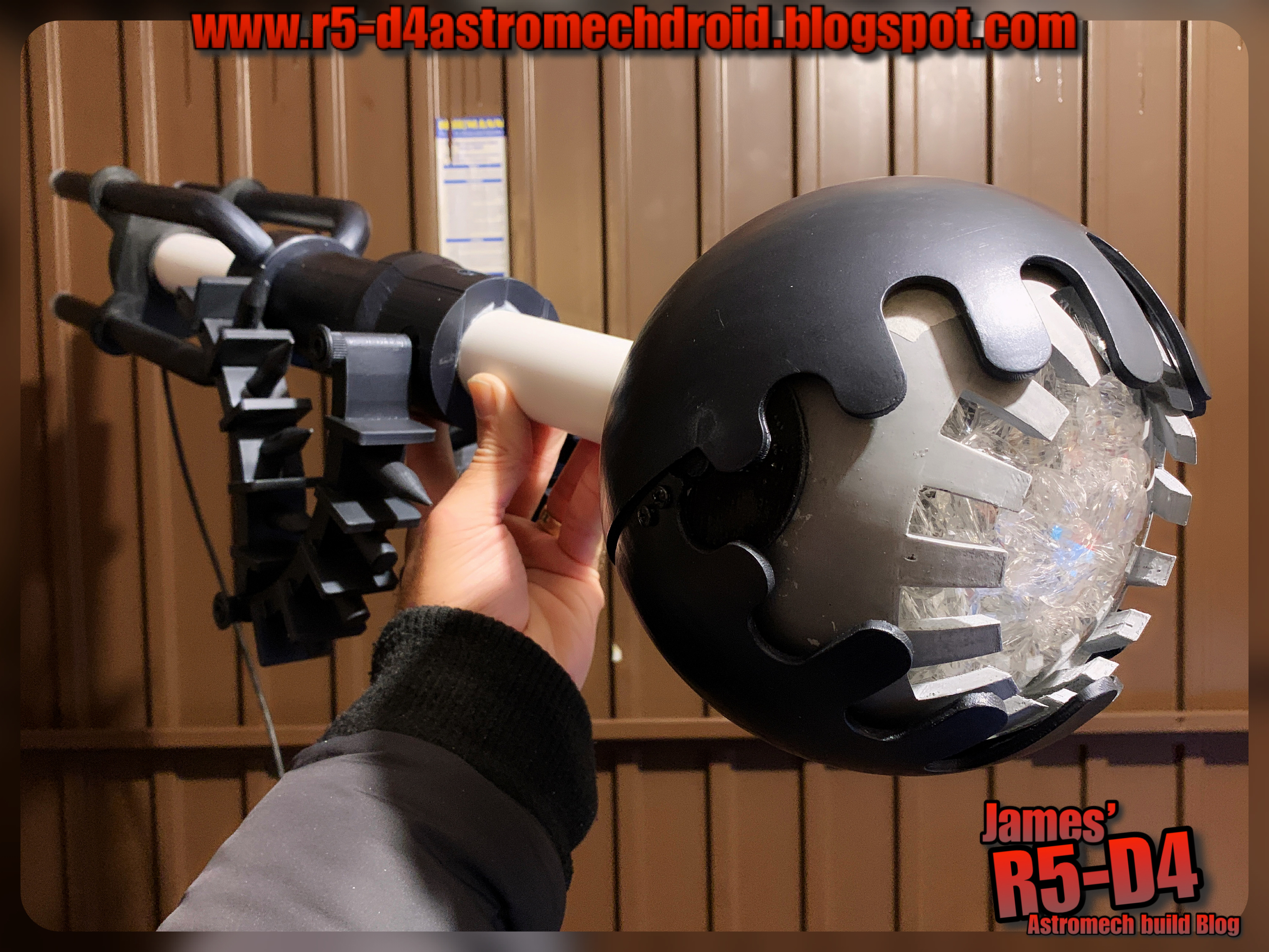
Once glued together and sanded. It was time to test assemble everything so far made.
I found some suitable length bolts and a steel length of rod. I drilled holes through the neck part and through the main PVC tube. Then the inner metal tube which will connect with the wall/door.
The next step was to disassemble it and start spraying up the pieces with the dark grey’ish paint, same colour as the eye lids. And here’s the reassembled parts. I still need to add the silver to these parts, as well as spraying the PVC tube.
The LED wires were trimmed to matched lengths and soldered together. A single fly lead will connect to both positive and negative wires and terminated with a plug.
The connection plug was wired to a lead that is threaded through the PVC tube. So the eye can be removed from the main shaft.
Some more pictures of the assembly.
I went through my speaker box and after a quick test, decided on one that was rectangular (out of an old laptop), this I will try to incorporate into the neck part of the build so the sounds will seam like they are coming from the eye itself. And here is the test install:
The PVC tube has a slot cut into it so that the speaker sits flush with the surface. I’ll be redoing this speaker holder.
I drew up an adapter that will be glued into the rear of the eye, and then the metal tube will be secured to it. The PVC tube will fit over the eyes rear hub.
The pivot points for the upper eye lid needed to be strengthened, as one already came off. So I’ve had to go away from authenticity and over to practicality and durability with a slight redesign. You can see the semi-circle just above the screws. There is a smaller version on the other side of the iris.
Am not happy about the screw heads, but it is what it is.
Next up was operating the eye lid movement.
I sourced a Pololu maestro 6 channel board…. eventually, off eBay, as everywhere was sold out, or over priced with postage and shipping. But order was cancelled as they didn’t realise there stock level was zero! Refunded but now the hunt was on to find another one.
Found another one and ordered…..but the Post Office have delayed its delivery 😡 so I had to search for an alternative actuation unit, but again I was at the will of the Post Office 😩😩😩. At this rate the eye lid may not be able to be motorised!
Drew up a servo bracket to fit inside the rear of the eye to activate the upper eye lid. Version 2, fitted better and uses a SG90 servo.
….Pololu still hadn't arrived.
March 5th:
Mike had the angled bracket for the eye, so I drove down to his work for a day of testing and fitting 😄.
We first brought out the three pieces and assembled them together. Mike had marked and colour coded them for easier and future assembly.
We marked the spot on the front and then drilled a hole through. This was the upwards angle point needed. The eye does stick out a fair way from the door when speaking to 3P0, but we wanted to avoid this so as people wouldn’t bump into it when having photos taken. We weren’t happy with the angle either, so the this was adjusted using longer bolts and spacer tubes to increase the angle more.
Here’s a progress picture:
Mike’s a big (tall) lad, so the fact the eye position is not in his head bumping range, is a good thing.
This fitting, figuring out, re-fitting, then cutting down the tube lengths, drilling locking location holes in the tubes…… took us about 5hours!!
Once finished I had started cutting down the tubes to fit. They didn’t need to be as long after all.
The tube can now be finished off with painting. And a collar/back plate, needs to be drawn up and printed to cover the whole in the wall.
I got home and made a start on primer painting the last pieces, the tube ring and the PVC tube.
Late March 18th:
The back plate had been printed and painted, along with the rest of the last pieces.
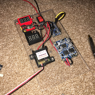
The PIR sensor unit that will hopefully trigger the sound and lights (& servo if the boards arrive in time), needed a housing and a position for it to be mounted in. I wanted all the electrical/electronics to be combined into one unit for easy of assembly, so using a design I had already, I modified it into a sensor type unit that can be pivoted and rotated to best suit the location.
I had also read that narrowing the line of sight helps with the sensor not triggering unwontedly. So the sensor housing has a tube over the front of it.
Early April:
With weeks left and no sign of some of the electronics, I have had to admit slight defeat. The set up for the sound and light activation wasn't working when triggered at the same time??? So it looks like they will have to be separate. Tried getting the servo to operate, but the circuit board is not a momentary switch, when I saw it I thought it moved and returned the servo when pressed/released.
This is testing the PIR sensor to trigger the sound via relay switch (centre of picture). PIR on the right.
There will be an event report that has/will follow detailing/reviewing Celebration. This will include more photos etc, so don't forget to scroll back through this Blog, like, share etc. I hope this behind the scenes was of interest to you. Please leave a comment below.
The wiring is there for future upgrades, probably better suited to an Arduino set-up, and for someone who knows what they're doing.
All in all, I am 90% happy with the finished item, minus the not working bits.
I hope you enjoyed attending Celebration and that you were able to have photo's taken with the display.





![new [yellow] cable clamps installed](https://blogger.googleusercontent.com/img/b/R29vZ2xl/AVvXsEj4777JvyLwKXlj10euqQOyYYAteDlCEUfa_eC3GqHQjOZ9lFbRSdNpzq58iypRHeroiVffnv0zJT_j9SeXiYBR0uGezIE4QdvEQiusi4cvja0Sd-rZG-RwrJrx01tupxFm2eJX524Dx1w/w200-h200/IMG_6272.JPG)
![new [yellow] cable clamps installed](https://blogger.googleusercontent.com/img/b/R29vZ2xl/AVvXsEj72TgDacBKBJEjssGu67_YT0BPilt9T12Qqg4lAOLbjIHPqyCMtSy_j39S2kX6LNxSv4ueXUGRCn_8R2E1ovoNctyu-OoSonrSbWaORH3EV3Htc38BkACsHHHdUyfMH_VQPzqI6HIE8bA/w200-h200/IMG_6273.JPG)