Showing posts with label switch. Show all posts

July 07, 2025

R5’s Bad Motivator 2025

 February 2025.....

Back on it again these last few months, waiting for delivery of different components to get R5’s bad motivator setup all working from one switch off the RC transmitter.

A new receiver paired to use a different channel not used on main body, worked when bench testing, but didn't work when both receivers were powered up. So it's back to the drawing board on this.....

An Adafruit sound board, mini amplifier, voltage regulator and utilising a speaker out of my parts bin lol.

Then 3D printing of brackets to mount these parts.

Then one new momentary servo controlled switch to control the adafruit sound board, and one on/off switch for the ‘Bad Motivator smoke setup’.

March 09, 2024

Treadwell WED-15-77: Part 25

 March 2024

I started this build back in November 2021:
Link to part 1 and now it’s coming to be completed this year 2024.

I will be creating a page viewable via the top tabs (PC) or via the drop down menu on your phones which will have links and photos to these posts.

This month:
  • Spray Painting
  • 3D printing
  • Rubber track moulding (YouTube)
  • Re-assembling
  • Electrical installation and testing
Painting the base:
I stripped the base of everything not made of wood lol, a pain, but it means I don't have extra weight and also I don't have to worry about something getting knocked by accident.
I then masked off the paint I wanted to keep and sprayed the bare wood with primer.

Some of the area's not sprayed are because these are going to have panels covering them, as painting neatly wouldn't of been easy. Here’s the masked off areas, spray primer work.


Once happy with the primer, I applied the blue paint.

A clear coat was going to be applied once dried, but the order didn't arrive, so this will have to be done at a later date.

Painting extras:
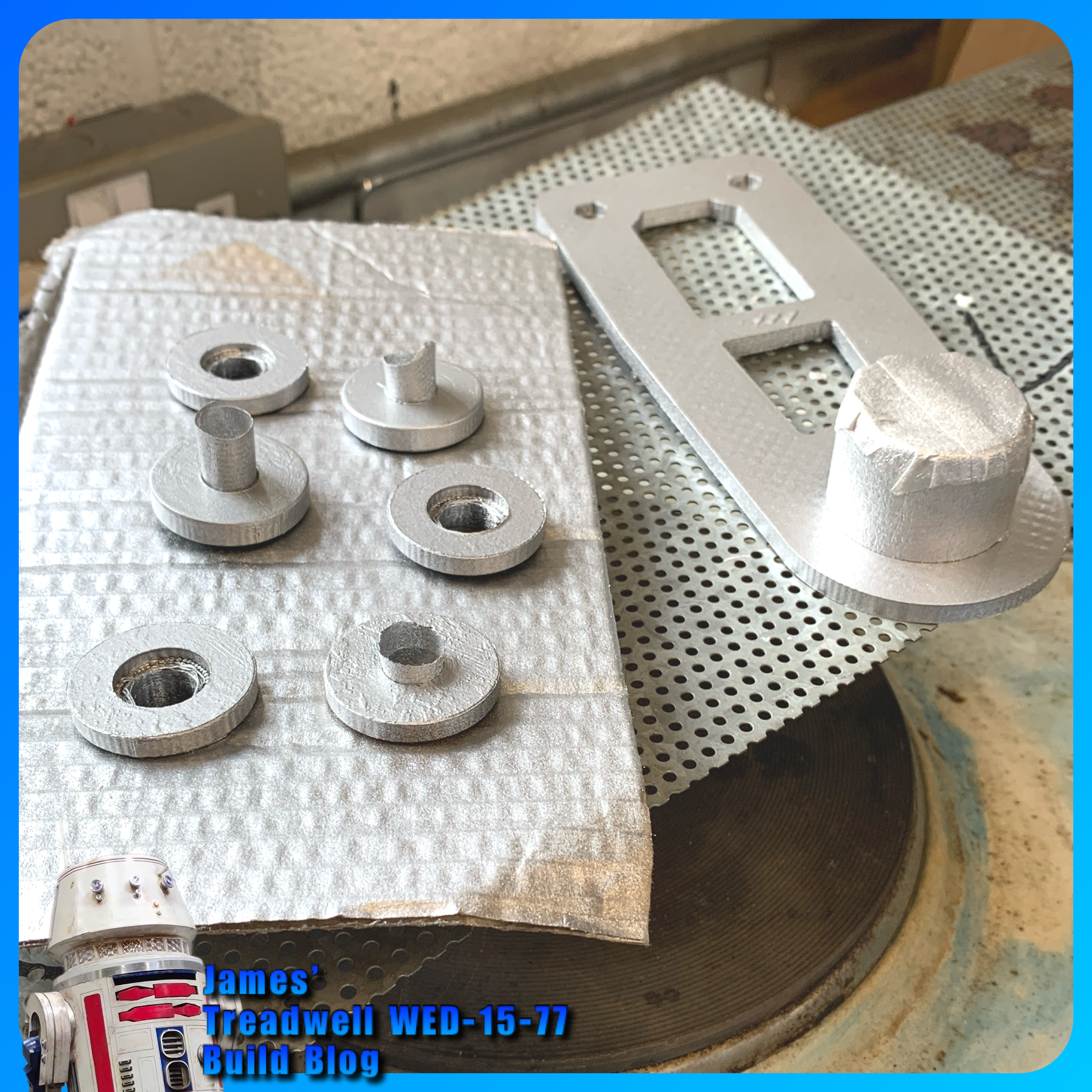
The one remaining wheel, plus the front wheel brackets and the lid supports, all got a coat of silver (not Plasti-kote) paint.


Also sprayed up were these missed wheel bushes and the mast base support.


Servo connections: block plug or just loose.
(Planned work, now next month’s schedule)

Tracks:
Ordered a single batch of two part mix of the mould mixture, to create the tracks with. I thought, if I need more, I can buy more.
The new track mould I printed last month didn’t print out very good (lifted off bed so not flat). Later, after a few failed prints, I found that the nozzle wasn’t as clean inside as I had thought, even with hot and cold pulls. So I didn’t reprint it as I already had two moulds anyway.

I used my original moulds (green filament) ones. Dusted with talcum powder as a release agent. I had seen this done, but don't think it works too well in this application lol. Read on for what I eventually used.

Here are the track moulding in progress. I made a video of this now up on my YouTube channel.

In the video, the track that couldn’t come out of the end of the mould was due to the filament that didn’t have support and had sagged, so the fluid mix was absorbed into it, bonding it together.

This part of the mould has been removed (cut out) and sealed with superglue.
Only one of the two mouldings poured, cured, bit disappointing really and don’t know why?? = after a few more attempts, I figured out that the mixture wasn't mixed properly and so hadn't cured properly.

Here is the joining plate with two ends, of already moulded track in position. Mixing up and pouring into this, joining plate, joins these together.

The poured join. Inside doesn't look great, but that's not important.

This was another poured moulded section.

Here is all the track made so far, these will all be joined when the second delivery of mix arrives.

The mixing and moulding process improved as I went along. I now have enough moulded to complete one full set of tracks, but will have to order a second batch of mixture.

Guide teeth:
I did have a go at moulding a ‘guide tooth’ onto a piece of track.
This first attempt, didn't work. The rubber didn't bond to the back of the track like it does with the joining sections, as I had expected. Once released from it's mould, the thickness (height) effected it's ability to flex with the thinner track when moving over (around) the drive wheels at both ends. So am going to have to look at something else or another mould idea.

Glue:
I did find and test out some special loctite glue which can be used on rubber.

This seems to work, still testing, but this could be what I need.

Mould Release:
Here’s the mould release agent I used, found a can in work:

The following picture was the last of the mix I had to bond together two pieces of the track. The rest went into one and a half track mould.

Video of the track coming out of the mould on my YouTube channel.

Test laying the track on the wheels:


Re-assembly:
As the build progressed, little snags appeared. One being my choice to use nylock nuts and washers to secure the front wheel brackets. The protrusion restricted the required clearance and they would catch on the inside face of the wheel.

Plus i needed to trim the bolts down in length, and use normal nuts with thread lock.

Not to waste the nylock’s, these were swapped over on the mast base support bracket.

Electrical:
I needed to move the power switch to the outside panel for ease access. This meant unsoldering the switch on the panel, adding a new plug connection and fitting the switch into its new location.

I drilled a dia 20 hole and fitted the switch just behind the mesh panel.

I finished off adding the power cable from the battery to the board, via the switch. And (test) connected up to the battery……

…..we have lights on the components.

Will the next Blog post be the final one…..????

March 06, 2021

R4-D4 dome - Life-form scanner - part 18

Re-wire switches:

The two switches that I had, just inside the opening of the dome, needed to be relocated to just clean up everything. These switches controlled the 'fake' electronics panel LED's as well as the Holoprojector light LED.

Am thinking that the Holo LED will be controlled in the future via a remote, to increase it's brightness when needed.

.....next up....

Painting of parts:

I had applied filler primer and once dried, sanded lightly the components for the LFS system.

I wasn't 100% sure what colour would be best for the internal components of R4's dome, but as I had already sprayed the lid panel matt black. I decided that the main inside panel would work better this colour than say white.


The lower servo lift was also sprayed up black.
The servo cover & LFS screen, both got silver paint. The internal panels and top, got a dusting of silver to help highlight the details.

The screws I had inserted to keep paint out of the threads, I decided to keep, as they blended in better than the clean versions.

I then applied a clear coat and then some black to add to the weathered effect. The orange primer also appears to show through in some places. This isn't as bad as I first thought lol, as it actually looks like sand in the crevices etc..... result!

I then installed it all in the dome.


The bracket can be seen installed. Up next is finishing off the electrical install and then the Pololu controller and electrical hook up.

October 05, 2020

Teeces LED work for Mike's dome [August 2020]

27th August 2020


     A few weeks back I was asked to help wire up a set of Teeces LED light and add some LED's to illuminate the Holo Projectors x3.

R2 type dome getting some lights fitted

I fitted a voltage regulator to drop the volts down to 5v.

Teeces lights lite up
These are the main lights for the dome illumination.

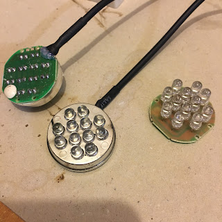
Mike also supplied some torch LED panels, which I managed to solder up wire connections to after figuring out why they all didn't light up with just one ground wire connected.
Torch LED units

After soldering these up, I had a thought about how to fit these into the Holo Projectors, without the dreaded 'Holo wire twist & break'. So I dug out my Holo Light units I made years back for my R4-D4 dome.

I did some updates to the LED holder, now that the 3D printer is better than the previous one lol and also upgraded the bearing holder.

Holo Projector LED holder

The bearing holder, is designed to be shaped with a file to be a tight fit into the rear opening of the Holo Projectors eye. The whole unit acts as a slip-ring arrangement, allowing the LED's to be connected and lite, but also allowing the Holo Projector to fully 360 degree free movement, without worry of 'Holo wire twist & break'!

Short video demo of new holo slip-ring

No more 'Holo wire twist & break'

Mike's dome only has two moving Holo Projector's, so these received these units. The third Holo is static. Nect up was installing them into his dome.

Panoramic view of inside the dome - LED's

Next up is to finish installing the power cables, the Teeces units & connecting up the power switches.......

wiring up the switcheswiring up the switches

And some pics of LED's illuminated.

illuminated LED'silluminated LED's

illuminated LED's from the inside of the domeilluminated LED's

Mike was kind enough to make this new tool storage box sticker, nothing wrong with the original lol, but hay....everyone should have their name on their tool box.

tool box stickertool box sticker


Interested in sign's etc, check out his website...

Click this link to his website ->>> Vinyl Designs

August 21, 2020

Transmitter switch cover update.....3D printed

 What a nightmare trying to match up the thread for the new switch nut on the transmitter. After three attempts, I decided to go with one of my original ideas, which was to fit a switch cover/lock. So after a few iterations, I settled on this version.

switch lock cover - sound switch

I recessed the nut into the lower part of the bracket, making it easy to fit onto the threaded part of the switch. The locking part is pinned with a sel-lok pin through and is not too snug a fit onto the switch arm itself. This just means that the switch can't accidentally be triggered, not that it could be as it requires an amount of actual force to click it. But it looks good rather than just having the nut.

I'll post up on Thingiverse soon. So click follow and/or on Twitter for notification of it going live.

April 14, 2020

Electrical System Update 2020 - 1.3 cable tidy

As I mentioned in my last post, I used yellow cable for the positive 12 volt side of R5’s electrical system. Connectors were soldered and heat shrink applied. Label's to identify were also added, before the expanding cable sleeve was applied to keep everything tidy.

Heat shrink was applied to the ends and I also added cable ties.


r5d4, electrical
Terminal block to distribute 12 volt power.


r5d4, electrical
Switch to control power to the feet motors,
having heat shrink applied over it’s terminals.


r5d4, electrical
The switches in place with heat shrink applied.
Cables with sleeving and labels identifying 24 volt power system.


r5d4, electrical
And a pic of the (almost) finished wiring setup.

It's all now looking really neat!