Post started 4th September 2025 - into October.

List of things to do is always a good start:
1. New idler axles x 6 off👍
New drive axles x 2 off👍
2. New correct Wheel spacers x 6 off👍
3. New motors x 2 off......................??? 👈
4. Signal booster fix. 👈
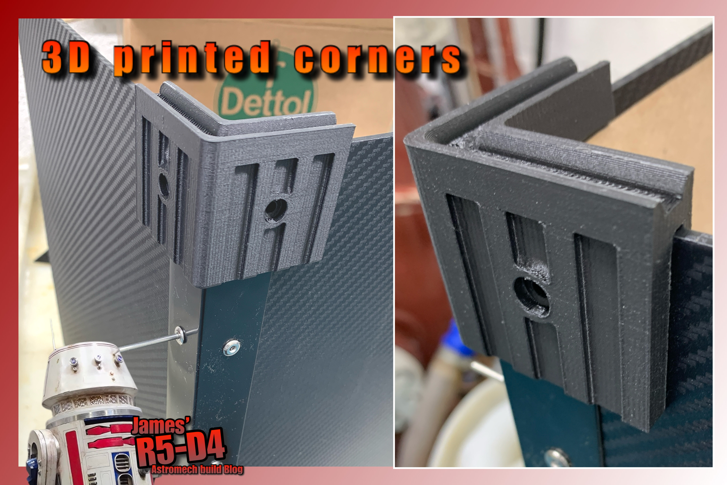
5. Mast box build - 3D printed parts etc. - click here to see Box Build Post.
6. Remove the original guide wedges from the tracks.👍
7. 3D print more new round track guides. 👍
8. Remove the paint from the drive wheels [sticky]👍
9. New front 'tension' blocks. 👈
10. Unexpected track repair......... but then a WIN!!! 👈
11. Volume knob. 👈
12. Fake antenna UPGRADE. 👍
13. LED's fitting to 'eyes'.
14. Constraining the ‘eyes’ to each other.
1. Starting with....new axles:
I bought an 8mm dia rod months back, but it was slightly over size so needed turning down on the lathe in work, to fit through the bearings etc.
First one turned out good [turned.....machined.....see what I did there 😂]. Only having lunchtimes to do this, drill a centre hole to then use a revolving centre so as to be able to machine the full length of the spindles. Next is to then thread the ends for the flanged M8 Nylock nuts.

I also needed to machine up two new longer drive axles, to allow for the wheel spacers. These are 10mm diameter, stepped down to 6mm dia for the shaft coupler. No reason really for the 10mm dia size, except that this was going to be the size for all the axles.
2. Wheel spacers:
On closer inspection of the alternative WED base droid, seen in Mos Eisley ally way, WED-9-M1 (Star Wars Fandom), you see that the tracks are spaced away from the body!
 |
| WED-9-M1 DROID |
So I had drawn up and 3D print off spacers, to match. Not sure how, but I got the diameter different, so had to reprint these. Not sure yet if these will be free rotating or if I will glue them to the wheels.
Pic from July 2024:
 3D printed")
3.New Motors:
A possibility......???
My thoughts were that perhaps they wouldn't be up to the power needed. Even though testing proved they are.
4. Signal boosters:
I found that when WED was fully assembled, I was having problems with controlling his arm and head. One possibility was that the battery was low. The second was that [with my first time sending a signal over this long length of cable] the signal was too weak. So I bought two sets of boosters fly-leads to try 👍.
 |
| servo signal booster |
5. Mast box build:
I had already drawn up plans for this when I designed the head box. See independent post for more details.
6 & 7 Track guide wedges - DELETED:
The 'screen accurate' guide wedges, were unfortunately too stiff for the tracks, and weren't flexible enough. So had to remove them and replace them with the new 3D printed round track guides [POINT 7].
7. Track guides:
I tried a few different variables, one being a slightly tapered diameter, after my original 'cannon' style didn't work, I decided to try this [credit goes to Paul's Bots]. Link to Paul's tread/wheels build.
I need to narrow the wheels channel for better location of the guides. So more 3D CAD/printing required.
UPDATE: 16.9.25
The new inner wheel guides printed great on version 2. These were slightly modified for structural strength and because visually they don't need to have the slits in like the wheels themselves.
After testing, I will update the 3D wheel models to incorporate this addition.
Here are the new wheel inner track guides, in black, glued in.
 |
| idle wheel with inner track guides |
Test first guide popped into place on the track.


So a total of 140 were printed off. 80 off each for every other groove.
8. Drive wheels paint removal:
The paint reacted with the curing rubber had became sticky, sticking to the tracks. So using sand paper, I removed the thick paint from the outer diameter faces.
9. Front 'tension' blocks:
The axles for the two front wheels were long enough, so I just altered the [3D printed] inside face that has the nut recess, so that a Nylock nut can secure the axles in place.
The location on the base has to be repositioned as the original tracks were a bit too long, requiring some woodworking alterations.
10. Track repair/replacement:
It wasn't on my original list of things to do, but on removing one or two of the 'track guide wedges', on an early join [one NOT overlapping] the joint broke. So I ordered some more rubber mix, but repair work will be put on hold as....... 👇👇👇
New Tracks:
11.Sept.2025
I thought I'd have another search inline for the tracks [super-charger timing belts] and found some here in the UK [at last]. Decided to bite the bullet and purchase a pair.

Click picture for link to Bolton Engineering Products.

I have no affiliation with this company, am linking for future builders.
The calculated cost of me making my own tracks was over £100 in total, not including the time to design up and 3D print off the moulds etc. The fact that they are also NOT internally web meshed, didn't fill me with confidence on they're lasting performance. They would still be ok for 'display' purposes.
UPDATE: 16.9.25
Belts arrived and I couldn't be more happier 😊😊😊😊😊
It may sound strange, but there are certain things that, for reliability, need to be sound. The fact that Tread needs the tracks to be 100% dependable/straight/strong, means that driving him with confidence is now a guarantee.
11. Volume Knob:
Still not as loud as R5, plus it does need to have a noise suppressor fitted. So whilst searching for ideas, I found this for drone fpv video feed interference suppression.
I fitted it, after some testing to find the cause, inline with the mini 'step down voltage regulator.'

And of course, I had to CAD up a bracket for it to be mounted onto the control board. The volume still isn't up to the loudness of R5......
12. Fake Antenna base: [6.10.25]
I wasn't really happy with the fact that the fake rear antenna, was made out of a steel piece of bar, no flexibility and defo safety concerns lol.
So drew up an adaptor in TPU that fits between the two parts as a test. This then fits onto the original base part. The upper section is also now a found piece of leftover carbon tube.
13. LED's fitting to 'eyes': [8.10.25]
This had been on my to-do list to bring some 'life' to Tread. Recently got hold of some large blue bulbs and sockets for them off eBay. Drew up a holder in CAD and 3D printed off some test versions, figuring out along the way how best to install them.
Originally it was going to be on the inside base of the head units.
Idea no2 was to mount the LED brackets to the rear of the lens window frames.


Tested the LED bulb behind the acrylic and it looks good, but needs to be diffused more????
14. Constraining the ‘Eyes’: (16.10.25)
The single-servo’d ‘Eye’, wasn’t very well linked/connected to the other. This bugged me!
So I needed a better way to constrain its movements.
I came up with the idea of installing the geared parts from a broken servo, into the unservo’d housing. So I re-designed the fake piston and connected both servo horn arms to it. Making the second ‘eye’ constrained with the servo controlled one.
UPDATE POST WITH picture(s)..........
Almost the end of November, and still have a few last things to get ready before the annual Droid Builders Christmas get-together....
A weekend blitz on the to-do list including the mast box build, and the final piece was to open up the slot for the front wheel axle, and some new location plate holes.

All (99%) complete, ready for next Saturday…… display and testing lol.
This Build has reached 29 stages, so to round off, I'll post one last Blog update with loads of photos lol, to make it a nice round 30.
#treadwelldroid #droidbuilders #rebeldroidsnet #3dprinting