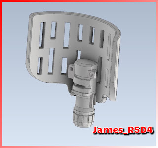
After the test fitting of the servo, I was able to better define what was/wasn’t needed and what changed I needed to make. Some of these were just for aesthetics, others to better suit the servo and positioning of it.
These included:
- Adding a small slot to one of the front grooves to allow the servo location tab to slot into. Just to add a bit to secure it.
- Moving the position of the servo further forward towards the centre of the scanner.
- Simplifying and standardising the design a bit more.
Next up was to design up a coupler for the servo to connect with the aluminium tube that arrived today.
This will use the servo screw to secure it and then the coupler will be a push fit onto the tube.
After printing and test fitting, I had to concede that this servo was actually TO small :D never mind....... onto plan B.
As I know that the servo attachment fitted onto the aluminium tube, I redesigned the outer surfaces and combined them into one file.
I've already got a lift system idea, and have some electrical/electronics to get together. So planning and building work continues.
And the printing has begun...
Hour and a half into the print gets you this far lol, 0.1 layer height.


No comments:
Post a Comment