

I created a separate Blog page for the building of this droid, but have decided to include it now on this so that all the info can be found in one place.
My original intention years ago was to build a Mouse Droid [MSE-6], as seen in the original Star Wars film, but this project got put on the shelf. So with COVID lockdown and needing a project to occupy my free time, I decided to re-start this one. Only this time I had decided that the GOUD-4 would be more fun/interesting/unique to build.
I've been a member of the Mouse Droid Forum now for a few years, ready for starting my MSE-6 build and now they had a section for this new droid seen in 'Solo a Star Wars story: in the Control Room on the Pyke controlled planet of Kessel.
Beginning:
So to start this project I had to finish off fixing up the donor RC car I was given a few years ago [pre 2019].
A friend from work gave me this a few years back, (thanks Steve), but I had just enough to make a start on it, clean up time.

I did find a stone wedged between the gear and the belt, which explained why the teeth are a mess and the belt ultimately broke.
Good news is that I was able to track down the information needed to repair the broken parts and move this project forward.
~~~~~~~~~~~~~~~~~~~~~~~~
So I spent some lunchtimes, cleaning the chassis of this RC.
I started to strip the car down piece by piece to service the broken/damaged parts. Namely the rear differential and the belt(s). One of them being broken. A stone had got trapped between the belt and the gears and chewed up both, breaking the belt itself.

The chassis was, I thought, a Schumacher SST '99 Pro, did a bit more searching to find it could be a SST Sport. But it could also be a Pro.... or a ‘98....??? As some parts still didn’t match up.
Thankfully the replacement parts I had bought, were the same!


I gave everything a wash down with an old toothbrush to get rid of all the dirt & dust.

This is the damaged differential and needed to be replaced.

This is the good one, it just needed to be stripped down and cleaned up, old dried grease to be removed & then re-oiled and re-assembled.

I found the belts, main gear and new differential online & on eBay.

All (mostly) cleaned up and re-assembled.

Here's the new differential fitting back into place.
Next:
- Wheels & tyre's
- power & controller check
- probably a lot of other things I'll find on the way 😄.
Wheels & hub adapters:
2020: My new wheels & tire's arrived and with them the next challenge. They don’t fit my car! Was hoping that the pictures were just generic, but no, so online I went looking for wheel hub adapters...... Found some, but at about £25 for a single aluminium part, that I wasn’t sure would be right. Others from China would take a few months which again, might not fit. So I got out my Vernier's and got measuring up. Drew up two adapters (front/rear) and test printed them.

The red/orange piece inside the wheel and the other side one to the right of picture, are the version 1 rear adapter hubs. These required a few more changes and finally, version 4 are now fitted.
Rear wheel adaptor:

The hexagon nuts are a push fit. The hexagon hub is not.

Don’t mind the wrapped wheels, I just didn’t want them getting dirty lol.
Next up was the front. These need sleeves to locate them, but again had a few issues. So decided to redesign with pin location hubs.....as looking at the exploded view diagram, is what should of been behind the hex adapters. This was another surprise as these are taper friction located....????
* Found out via more research that these taper friction hubs were only produced on the very first range of these cars.....so very rare!

So the final design combines all the above lol, except the pin part.
And here’s the front hub adapters.

Again, don’t mind the filament colour changes lol. So just waiting on the sleeves to get here and then the screws to fix them on with.
Front Panel:

I created this from a sketch/plan that had been uploaded to the Mouse Droid forum by: Daleacre
Due to its size, I had to section it in half. Not the end of the world & actually made printing easier, not having to leave it running overnight.

I left checking it to long when it got to the ‘holoprojector’ and the filament got caught, so had to abort. Luckily it stopped on a layer that I could work with lol.
So I did some changes to the holo that I was more happy with and that could be fixed to the already printed panel. This will be incorporated into the original panel as one stl file & will be added to my Thingiverse page once completed.


#5 Front Panel:
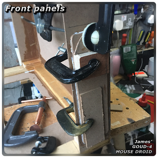
I also drew up a slotted jig to hold the slots inline when it’s time to glue them together.
As my first attempt needed to be glued together, I needed a jig to make sure both parts were aligned correctly. Found a sheet of wood and some dowels and hot glued them in place.

* for my revised version, I think I’ll extend the cut line up so the slots are printed as one section. This would still fit on a small bed like mine.

And once glue had dried...

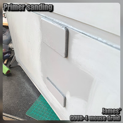
Next up was to file the joins, to make them all flush. This was not as time consuming as expected lol, mostly because of the slot locations tool. Once happy everything was flush, I started on sanding the surface to remove layer line ridges etc. I then gave it a first coat of filler primer.

Once this had dried, I went over the panel again with a file and sandpaper to the areas highlighted by the primer. The one annoying area as mentioned before is the one slot that came away from the print bed. It needs a bit of work doing to bring its angles together. Using a flat file, I managed to bring the edges roughly back inline.
A second coat of filler primer was then applied.
Whilst this was drying, I started cleaning up the print lines on the holoprojector. The revised version will have round grooves instead of flat bottom ones lol, making them easier to file out.
I noticed on one of the pictures that there could be another detail next to the main holoprojector, so I’ve updated the design, and also printed off the part to glue onto my panel.
I've also reduced the original protrusion of the main holoprojector and have now included a retaining ring, which I'm planning, will hold a cabochon in place.


Pic of holo, cabochon & retaining ring
Much happier with this shorter holo. First test of retaining ring fits tightly, but the depth needs altering to get a tighter fit against the cabochon.
#6: Frame bracket supports
Whilst looking at the cardboard template for the main brim, I needed a way to support everything onto the RC cars frame.
The two main ‘shell’ frame supports on the suspension mounts was a logical place. So after some measuring, width, I draw up a bracket in CAD.
I then printed a test piece.

After looking at the frame, the height needs to be reduced, so have modified this version to be lower in height.
#7: Lower shell & frame
Working with what I have in my garage, I started cutting up wood that will be used for the lower body panels. I had made & cut out, cardboard templates as a guide from the plans.


The joints will require strengthening once assembly starts. The above picture is of course, upside down & will require the middle of the board to be cut out. The board also needs to be made thicker, which will come later on as I don’t have any wood the right thickness.
Monday 22nd February 2021
I made a start on gluing up the panels, using PVA wood glue. I had added chamfers to the edges before hand. I used hot glue to help keep the edges in place until they had dried.
Tuesday 23rd February 2021
The glue had fully dried & was holding, though I wasn’t going to risk any breaks lol so handled with care. I added some more PVA glue to the joins, to fill in any gaps.

Later, once dried, I made a start on marking out the wheel arches. Can’t wait to cut these out.
#8 Front Panel - sprayed up:
Glued the holoprojector onto the front panel and after removing the cabochon, applied a few more coats of filler primer.


The ring also got a coat of black. And once dried on the heater, the cabochon & the ring were put back inside the holo.

#9 Front Panel & Wheel trim:
Added brass inserts into the rear of the panel to be able to secure it later.

Drew up these wheel trims to hide the white rims lol

Had to slightly modify the rear clips to better grip the trim to the wheel.
#11 Update..... electrical/electronics
I thought I'd have a quick look and see what I could do now that I have a bit of free time.....
- I cleaned up the motor controller, as was a bit dusty/ingrained dirt.
- Looked at the battery terminals and how I can swap them for connectors I already have to facilitate connections.


- The battery harness that I drew up years ago, needed some small changes for it to be a better fit for the battery. Also the opposite end fixing straps need looking at.
- Still need to fix the suspension struts or convert them to solid rods.
With the above list, I found some M4 threaded screws that I can use to secure the wheels to the hub spacers.
I also went looking for a transmitter/receiver.....
and found this Volantex EX6 for a bargain price! This is the 6 channel version. It didn't have to be as advanced as the EX7 (that I have for R5), but I still needed extra channels, rather than a trigger grip transmitter.
 |
| Volantex EX6 Transmitter |
#12 - Belt drive tensioner system:
As the front belt drive is 'loose', not sure if I have the right belt, due to not now knowing WHAT version of car this actually is 😄. I decided that I wasn't happy and after some investigating, decided that I needed a belt tensioner to remove the slack.
I looked at buying one, but there was the chance that I'd just be wasting cash, so I decided to make my own.

Measured up the height and using a piece of cut to length steel bar I had, and a piece of the Aluminium tube I had from R4's life form scanner project [click link here for this over on my other Blog]

I assembled up this functional belt tensioner. For testing purposes, the unit is glued in place, but seems to be holding up ok.... Time will tell.
#13 - Lower body work has begun:

Bit the bullet 😃 and started cutting out the wheel arches. I had marked roughly the positions months ago, but as there were a few missing pieces I wanted to sort first..... belt tensioner [see prev post], and also the new wheel bolts that I needed to sort out.....oooh and the suspension struts.... THAT's for another post lol.
The grey version in the first picture, was a sample print, to get an idea of location positions.
I redesigned the support frames that will mount on the RC’s body mounting points.


So the SST is low!!!
So low that with the addition of the droid body to be built, would all weigh it down and probably ground it! I did look at stiffer springs....but thought that if they didn't work, that would just be wasting cash.
I needed to 'fix' the suspension in place....which would actually mean, removing the springs altogether!


So I measured up the length of the suspension and drew up a tube to replace the spring. These fit great! Of course....it still needs to be driven tested, but it's not going to be driven around like a proper RC car, so hopefully, the removal of the springs won't cause a problem. If it does, then it's onto plan 2 lol.


Which explains why I couldn’t find any info on why mine weren’t ‘normal’ drive shafts.
 Trying to find info on the Schumacher FH1000 speed controller is hard. Yes there are pictures of it online, but searching for the instructions for one are non existent.


….still waiting to hear back with any info. But I do now know what the H & N mean??
 The picture shows the two outer panels . These all have a raised panel on them. I cut out the first lower section panel and then the two pieces were glued together with some weights to help. (Have to remember to take a pic on the next one)


Glued and screwed together. To keep weight down, these are just strips with 45° angles cut to mitre up with the adjacent pieces.


Finished off the lower frame.

Then came the glass fibre matting and resin.
 I added some blocks for strength and support. These will also get fibre matting applied.

The first end piece glued into place. Whilst the resin is setting, I was measuring/adjusting/cutting out other pieces of the body.


Used PVA wood glue to hold the panels in place, before applying glass fibre & matting. Used some sized pieces of wood as support / strengthening between the panels.
 Marked the hole positions for the holoprojector panel to be fitted to.
 This was then glued and braced in place to allow the glue to dry.
 Next up was the upper and rear panels. Whilst these were drying, I layer up more fibreglass matting and resin to the joints to strengthen them.

 Cut out the raised panels for the front. From the images and weathering, the corners are slightly rounded over.


Next up, adding woodwork to help with strengthening the supports.


Next up was more gluing up of panels.
I then glued the centre section into place. This along with the top plate received glass fibre matting & resin for structural support.

For the rear, as it's not seen, I wanted to do my own thing. So I used a scaled design of my own and after inserting some brass inserts, it will be secured to the lower rear panel.
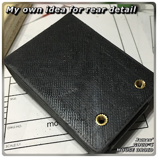 There will be three 'tubes' that will fit into the slots and then pass through into the rear panel above it.

It has an unusual profile which I liked, so used this outline to mark and cut it out.

The heat sink was then secured onto a second sheet of wood and glued in place on the inside.


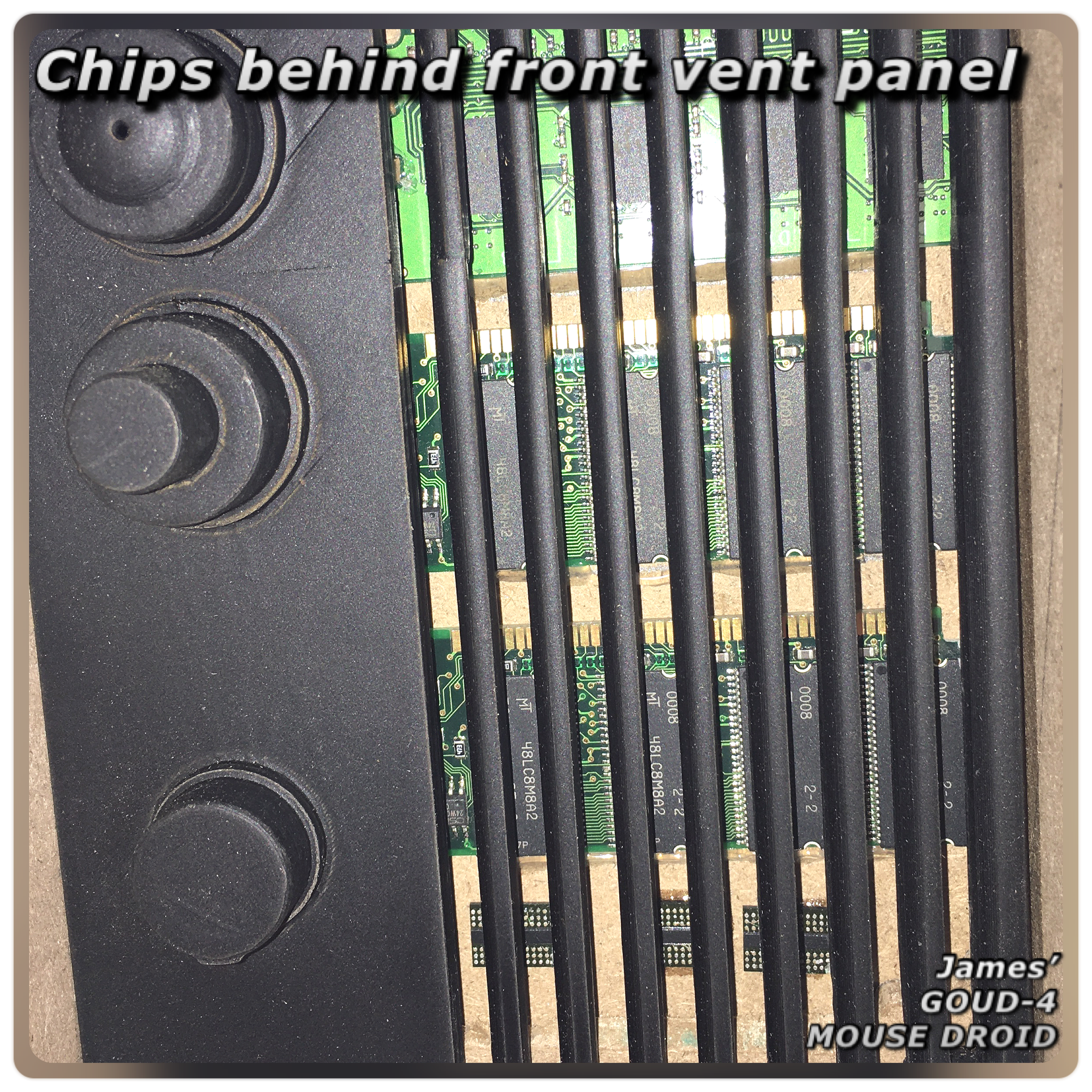
The second from last piece of work done, was again a little nod to the original MSE's, but with a modern twist lol. I dug out these memory chip boards I'd salvaged from old PC's and cut them up to fit behind the holoprojector vent grill.
 Using double sided sticky tape, I attached the cut up pieces to a rear board, which will leter be glued into place.


The plate (maybe) glued onto the bracket.


The above picture also shows a few steps ahead of this build.


 In the above and below pictures, the side angles of the skirt are having extra strengthening strips glued in place.
 The skirt frame also had additional support structures added later.

 So that the panel stayed flat, it was clamped to another piece of wood.

The hole on this panel has cables and tubes etc coming out of it. The second opening on the other panel (top of picture) will have a lid fitted later.

Angled supports added, PVA glued in place before having matting and resin added to strengthen it all.


This was then sanded and shaped and a bit more applied to fill out areas missed.


Masking tape was applied again to prevent the body filler sticking to parts not requiring it to be. Then applied a few skims of filler, using the top panel as a straight edge.


After the wood had dried, the surface requires a light sanding. You can actually feel the hardness of the edges after the wash has dried.


You can see the wood fiber's standing up.


Once the paint was fully dried after a few hours, I made a start on sanding.
Using 180 grit paper to start with.


Once dried, I gave it a light sanding before re-applying another coat of black. I don't usually use masking tape as an edging, as it does tend to allow the paint to bleed, but it didn't do a bad job. The upper coat will cover over anything not 100%.
Discussed the upper body colour with fellow builders, so just need to go and buy some.


Enlarged view.....


So either two versions were made or one or both could be mocked up for the photo in the book (which is a possibility).


Started with a saw blade and then used a knife blade to flush cut off the wood, see below.
 Once happy with new face, a light sanding was done.

Then on to the second part. Saw blade to cut to depth, before flush cutting the excess.

I marked and made a slight recess cut to make this panel which will be painted black later.

I then cut out this extra piece, sanded it and the body before gluing it onto the side panel.

I then added a strip to the inside channel face, as mentioned in last post. See below picture:

Once the glue and PVA wash had dried on the modified areas, I gave them a light sanding.
Wiped down the panels and sprayed the upper body with Matt white spray paint.

As you can see in the above picture,
there's not much ground clearance …..it drives well
#15 - SST Drive shafts:
Whilst searching and gradually understanding the history of the SST’s, I was searching for standard replacement drive shafts, when I found these on eBay.


Which explains why I couldn’t find any info on why mine weren’t ‘normal’ drive shafts.
#schumacherSST #SST2000 #Goud4mousedroid #mousedroid #rccar #soloastarwarsstory
#16 - Schumacher FH1000 speed controller:

I have read that they used rebadged versions from Mtroniks and I found a website with loads of information sheets for multiple manufacturers and models of ESC’s but non for this model. They do have a request email which I have messaged, just have to see if they’re able to find the tech sheet in question.
In the meantime, I decided to open it up and have a look inside. It needed a dust from years of grime built up. I used slightly damp & a dry cotton bud and gently wiped around.


….still waiting to hear back with any info. But I do now know what the H & N mean??
#17 - Upper Bodywork begins:
Over a week, using the plans created by Daleacre on the Mouse Droid forum, I made a start on cutting out the side panels.

This droid doesn’t have the same recessed lip like on standard MSE droids, [upper shell to lower shell], but in this found image below, you can see the lip underneath the upper body panels, not fitted properly on.

Made a start on the lower frame work. This will be the strength of the frame to be able to take any knocks and bumps.

Glued and screwed together. To keep weight down, these are just strips with 45° angles cut to mitre up with the adjacent pieces.
Saturday 10th July
Was a very productive day.
There are though a few old sayings, that I will now quote:
measure twice, cut once.
&….
Assumption is the mother of all f@#$*+s!
The plans I used for my MSE droid were the ones based on a 1/10th scale RC. Unfortunately, Daleacre’s plans for the Solo GOUD-4 droid aren’t [possibly the 1/8th which is larger].
This came to light when holding up the side panel to the base frame.
From what I had read I had assumed that his info was based on the standard 1/10 scale. The fact that the MSE plans are in imperial and the GOUD-4 ones are in metric didn’t help the obvious error in my thinking.
If you re-look at the black and white photo (2nd image), you can see the scale comparison with the remote controller that is sat on top of the channel (what would be the top of the original MSE). This gives an idea of size of these side panels. Again though, I'm assuming that these newer droids are based on 1/10th scale cars.....???
Not to worry, it was simply a case of cutting the two side panels down in length. And then modifying the rest of his plans to best suit the 1/10th scale frame size.
Once that was sorted, it was on with the build.


Finished off the lower frame.
Then made a start on fitting the side panels. I screwed in this angle bracket to be able to clamp the side panel in position.


Then came the glass fibre matting and resin.


The first end piece glued into place. Whilst the resin is setting, I was measuring/adjusting/cutting out other pieces of the body.
#18 - Upper Bodywork continued:
Continuing on from fitting the first side. I cut out the two inner panels. These required alterations from the original plans, due to length, but also the front panel I had drawn up from the plans and 3D printed, wouldn’t now fit , as this had also been scaled off Daleacre plans.


Used PVA wood glue to hold the panels in place, before applying glass fibre & matting. Used some sized pieces of wood as support / strengthening between the panels.


#19 - Upper Bodywork continued:


I marked up guidelines to help placement of them and glued them into position, held with clamps.
The small upper piece.

Whilst these were drying, I measured up and cut out the upper side raised panel. Which was then positioned and glued on.
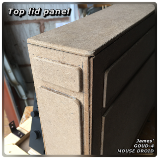
 There are two additional small pieces that fit on the lower side panel, these I’ll add later. Last piece was to cut the top ‘lid’ panel. I’ve rounded the edges.


#20 - Upper Bodywork continued & subframe brackets:
This week has been designing and 3D printing a spacer for the subframe (body to car), in order to get the stance of nose down, rear up. I first printed angled spacers to achieve this, but this wasn’t very good, because the subframe at the rear, wasn’t supported enough in the raised up position. So instead, I drew up a spacer block to fit underneath the subframe which was glued to it.


I used cut down dia 6mm carbon tube as the location pins to fit onto the cars body frame.

Next up, adding woodwork to help with strengthening the supports.


~~~~~~~~~~~~~~~~~~~~~~~~~
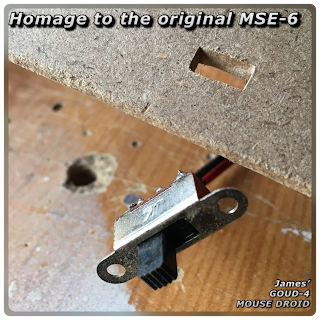
Original MSE-6

I wanted to pay homage to the original MSE-6's by adding the power switch to the skirt. The original Schumacher FH1000 switch on the speed controller, had seen better days and was corroded. So I used a new [old] one. I cut off and added a plug so it can be disconnected from the car, when the car is removed from the upper body.


Next up was more gluing up of panels.
The top panel being glued on and clamped to dry.


For the rear, as it's not seen, I wanted to do my own thing. So I used a scaled design of my own and after inserting some brass inserts, it will be secured to the lower rear panel.


Whilst on the rear panels, I also wanted a recessed something, so found this cool looking heat sink in my box of tricks that I had saved years ago.


Here's a picture of the new rear parts.

For the top panel, the rear area has wires etc protruding out of it. They then hang over into the 'channel' part of the droid. I wanted something there for them to connect to, so using an offcut, I made up this piece and glued it down.

The second from last piece of work done, was again a little nod to the original MSE's, but with a modern twist lol. I dug out these memory chip boards I'd salvaged from old PC's and cut them up to fit behind the holoprojector vent grill.


And finally, onto the last leg of this construction part of the build.
I cut up the front panel and spacer/support blocks and glued the inside panel onto the channel section.

Once this is dry, I'll fibre glass matt the joints before applying the outer panels.
.......extra, I found these two batteries for an old transmitter, think they'll come in handy for the sound system.

#21 - 7.2 v Battery brackets:
I needed some new brackets to hold the 7.2v battery pack in place.
I drew up a version similar to existing ones.


#22 - Rear I.D:
Whilst searching on eBay for parts, I found you could get number plates for your RC’s. Now, technically droids don’t have number plates 😄 but they do have I.D. Info on them, so to help identify G4…..that’s his new name, I decided months ago, to draw up and test printed off some different ones.
Next was to draw up a holder/bracket. The first design was intended to be mounted on the RC cars frame, but the available mounting points were not a good place to be able to then see the plate. So I then drew up a bracket that would sit on the rear lower ‘skirt’ frame.


I included holes for two threaded brass inserts to help securely mount the bracket.

The plate (maybe) glued onto the bracket.
#23 - Upper Bodywork 95% completed:
Did some thinking and remembered Star Wars screencaps website. Thought, could there be any images of G4??? Had a scan through the Kessel control room.... and found two frames showing G4.... and even better still, his opposite side panel.

The images aren't great as he was moving, but it gives you an idea of what his opposite panels look like.
So I cut a panel roughly to scale and glued it down.

The above picture also shows a few steps ahead of this build.
I started with:


The hole on this panel has cables and tubes etc coming out of it. The second opening on the other panel (top of picture) will have a lid fitted later.
As part of the car to body supports, this panel needed modifying for clearance of the front suspension.

Angled supports added, PVA glued in place before having matting and resin added to strengthen it all.


#24 - Upper Bodywork 98% completed:
Another coat of body filler applied to edges etc.
Then next up was to fill in a few gaps. The top panel will be removable, but the sides it sits on were slightly uneven, due to manual saw cuts. Also making the panel removable idea came later on.
So I applied masking tape to the areas I didn’t want the body filler to adhere too, mixed some up and applied.
This was left to fully dry for a day.

This was then sanded and shaped and a bit more applied to fill out areas missed.
Once I knew this would work, I decided to fill out the inner side wall. When I applied this panel, I didn’t use spacers to evenly keep it apart, which I noticed once it had dried. I didn’t want to cut the top panel as it would show the unevenness, so the alternative was to fill out the side wall to the width of the top panel.


Masking tape was applied again to prevent the body filler sticking to parts not requiring it to be. Then applied a few skims of filler, using the top panel as a straight edge.
Leftover filler wasn’t waisted, it was applied where needed to spots.
#25 - painting preparation:
Once I was happy with the bodywork, next came the sealing of the wood. I applied a mix of PVA glue & water and brushed it over the wood. This helps to soak the PVA glue into the fibres and once dried, makes it hard. It also seals the wood for when it’s time to spray paint it.


After the wood had dried, the surface requires a light sanding. You can actually feel the hardness of the edges after the wash has dried.
I gave it a day or so to fully dry before spraying with filler primer.
Looking forward to the same smooth surface I achieved on R4’s dome.

#26 - Filler Primer & painting:
After I was happy with the sanding of the wood after applying the watered down PVA, I masked off the underside supports and side switch and started applying the filler primer. The wood didn’t really need it, as the edges etc were all joined & also the panel edges, but no harm in giving it the twice over (two coats).


Once the paint was fully dried after a few hours, I made a start on sanding.

Using 180 grit paper to start with.
Once I was happy, I masked off the lower section, the skirt, and applied some grey spray paint. This will act as an undercoat for the mat black.


Discussed the upper body colour with fellow builders, so just need to go and buy some.
#27 - Upper Bodywork - side panel update:
I knew that I had seen more images of this droid......it was in a video, that I remembered watching.
It was on the Star Wars website, called, 'Creatures & Droids- be Han the scenes'.......play on words 😄


And here is the image/screen grab, showing the opposite side of the droid!......bottom left.....


Looks like I need to do a bit of modifying to my side panel....... it also looks like there's another extra panel on the inside channel face, near the front.
Another thing to note, is the wheel base size….this is quite possibly NOT a 1/10th scale RC…??? Also the lower body section, doesn't match up with the visual directory or standard MSE-6's.....???
Comparing the above image to the one in the visual directory below…

So either two versions were made or one or both could be mocked up for the photo in the book (which is a possibility).
#28 - Final Preparation, priming & painting:
Made adjustments to the side panel.
As the size of the droid differs from mine, I made them similar in prepositions.


I then added a strip to the inside channel face, as mentioned in last post. See below picture:


Once the glue and PVA wash had dried on the modified areas, I gave them a light sanding.
A day later I applied primer over these areas and the rest of the upper body.
Followed, once dried, with another light sanding.


The top panel missing in this picture, was also sprayed up.
Next, wait for it to dry.
#29 - Sound system:
Dug out the electrical/electronics box containing the amplifier, voltage booster & voltage reducer regulator and the sound card board (later upgraded).
Started soldering up pins and adding new plug socket connectors.


Next up was adding the inside panels. These I had 3D printed and then painted off white to add contrast with the outside colour.
I then found the tubing and fitted some around the inside rear face as well as coming out of the opening.


Started soldering up pins and adding new plug socket connectors.

There are a few more bits I need to work on so will update this new page as and when. Designed up a bracket for the speaker which the other components brackets can be attached to, hopefully making it easily removable.
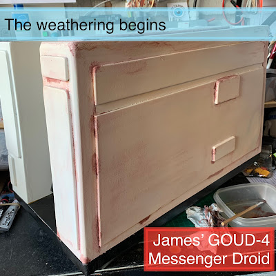
#30 - Painting / weathering:
Dug out my acrylic paints, all three colours and started to apply the weathering effect to the body. I started with dulling down the whole body with Umbra, then mixed in yellow ochre and then black mixed in.
I tried to copy the images I have and match G4 to them, the rest I just applied where you’d expect dirt and grime to appear.


In the past, I’ve clear coated the top coat of paint before applying the weathering, but decided to coat afterwards. If I want to add more weathering I can, but the main effect is now sealed in.
I then added the side detail strip. It’s a cut down piece of 3D printer channel cover that was the wrong size for mine. It’s hot glued into place for now, see how it lasts.


All finished up ready for it’s first event 2021.
G4’s first drive out:

YouTube links:
YouTube #shorts
https://youtu.be/KQfRkV
https://youtu.be/KQfRkV
Update: end of 2021:
The original 1800 battery [which was a found item] just couldn't deliver, so bought a new 5000 version.
Update: January 2022:
A new sound board was purchased as previous one required special sound files to be created (old). Also a switch relay to activate the sound board.
No comments:
Post a Comment