Showing posts with label R5-D4's Power Cables. Show all posts

April 14, 2020

Electrical System Update 2020 - 1.3 cable tidy

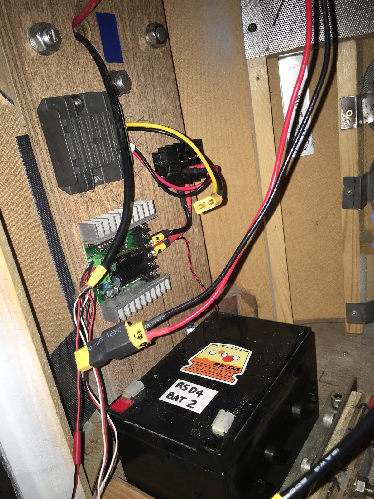
As I mentioned in my last post, I used yellow cable for the positive 12 volt side of R5’s electrical system. Connectors were soldered and heat shrink applied. Label's to identify were also added, before the expanding cable sleeve was applied to keep everything tidy.

Heat shrink was applied to the ends and I also added cable ties.


r5d4, electrical
Terminal block to distribute 12 volt power.


r5d4, electrical
Switch to control power to the feet motors,
having heat shrink applied over it’s terminals.


r5d4, electrical
The switches in place with heat shrink applied.
Cables with sleeving and labels identifying 24 volt power system.


r5d4, electrical
And a pic of the (almost) finished wiring setup.

It's all now looking really neat!

April 08, 2020

COVID-19 isolation at home - 3D design work

My work allows me to work from home, unfortunately the 3D printer is in work, so not able to print anything 😢 ......well.....it is their's 😆 lol

So I have been able to work on R5 and some other mini projects requested by friends.

Adafruit sound board
Re-re-soldered the contact pins on the adafruit sound board, changed them back to right angle ones. Easier for the leads to protrude out the side, rather than straight up for connections to the relay switch, for wherever it gets mounted.

Protection case for sound board
So because of the above, the 3D model had to be modified again to match.I added recesses in the base to allow the underside of the pins to sit in so the board sits flat.
Adafruit sound board, thingiverse
since been modified.....again.
3D models
Been working on other 3D models for myself and friends. After a comment on my Instagram about the above sound board holder, I drew up one for the longer version, which has a headphone jack socket on it.
Adafruit sound board, thingiverse


Next up was a holder for Paul's ESC unit. I had one of these he had lent me ages ago to try out in another project. So I was able to draw up a holder for him to test print one.
Th inside area was a bit too snug, so version 2 was a slight redesign and the addition of a rear bracket, tho this wasn't needed as the fit was just right.
ESC holder, thingiverse

And Paul was kind enough to send me some pictures of the unit fitted.

Recess' to allow the holder to fit over the top but not interfere with the cables.

Another club member wanted me to design up a mini slip-ring holder, for his holoprojector's.
This is still a work in progress.....

R5's cable management
R5 runs Red & Black power cable, as must builders probably do. His main power is 24 volts.
A while back (years) I bought some Yellow cable to match up with something....oooh yes, the 24 to 12 volt regulator. It has red/black wires in and yellow/black output wires for identification.

So rather than waste it, I decided that it would actually be a good thing to use for the 12 volt side of things. They're also now tagged with labels & clear heat shrink to aid identification.

R5's sounds
Got round to organising sounds, renaming them etc all ready to transfer onto the sound board. Then remembered that I couldn't connect the USB board as the files are virtual, as I'm remote desktop'ing to my works PC......aaaaaaahhhhh 😒
And for some reason, the USB sockets on this laptop are not recognising the drive, so will have to use another laptop.

March 03, 2020

Weekend work on R5 - TCD ,‘Trading Card Dispenser’ control box fitment

Last week I drew up a curved back, bracket to mount the trading card dispenser control box onto. I wanted its position to be closer to the TCD, ‘Trading Card Dispenser’, itself. The power distribution terminal blocks position had to be moved as the leads had already been connected. Still, it’s better as the 12 volt cables don’t have to reach as far round to the distribution block.

The main 12 volt cables still need to be connected up to the distribution block. The other pair of cables seen are to the dome motor, but require the speed controller to be fitted inline.

January 10, 2020

Electrical system update for 2020

R5’s original electrical system was set up as most are, with the purpose of general use etc. This is fine  but in R5’s case, I have to remove the rear hatch to power him on or off. This has grown to annoy me over the years lol.

So I’ve decided to make life easier by streamlining the electrical layout & re-positioning the switches to a more accessible location.

Below was the electrical board original position.
R5D4 astromech droid

I have already taken out the electrical board that was fitted to the crossbeam and uninstalled the components, Sabertooth speed controller, voltage reducer, distribution power block and switches.

Next up was to test fit the components to the side wall.
R5D4 astromech droid

The two switches are going to be relocated into the skirt recess. As the wood base is 18mm thick, I need to cut out a piece large enough for the main body of the switch to fit inside. And these will then be secured to a new blanking plate. In this case, a piece of Perspex.

I marked a position suitable and chain drilled holes for the opening.
R5D4 astromechR5D4 astromech droidR5D4 astromech droid

The last corner I had to grab a saw blade to trim it square.
R5D4 astromech droid

I made a start on cleaning up the edges. And as I had to finish up, made a template out of cardboard to get an idea of the size required.

Switch mounting plate:
I didn't want a piece of metal so I grabbed an off cut of perspex and using the cardboard template, marked and cut it to size. I then marked hole positions and drilled these too.

Here I test fitted one of the switches with the 'kill switch' cover.
R5D4 astromech droid

Happy to say that the skirt is deep enough not to be able to see the cover when it's in it's open position.

April 16, 2015

Sound board - installation complete 1.1

Made up some wood location stands, cut slot's into them and screwed them to some MDF base plates. These were then screwed into place.

I then made up a cardboard template of the metal bracket I wanted to make to secure the top of the board. Cut, drilled and then bent into shape, marked position on board and drilled a clearance hole for a bolt, washers, spring washer and a butterfly nut, to secure in place.

I then finished off some more wire's, soldering and connected these back up to there respective terminal blocks.
R5-D4,

R5-D4

R5-D4 sound system
The top securing bracket can be seen better in this image.
This lot took over an hour to complete!

December 16, 2014

R5-D4's Dome control system 1.1

Ordered my Dome motor the other week.
Along with a BaneBots wheel and the adaptors, required to combine forces.

The motor I ordered from Maplins, the wheel and adaptor I ordered from Technobot
(low stock levels)
Spent a few hours working on how best to fit it.

September 10, 2014

Electrical: Batteries arrive & more installation 1:4

Sunday I started sorting the servo leads, firstly by cutting off the end female plug as the wires are fitted into terminal blocks on the speed controller. The receiver get's it's power from terminal blocks on the Speed Controller.

Monday, my.....sorry, R5's Batteries arrived. They tried to deliver them last Friday, now that's quick service!!
R5D4 batteries

I placed them into the base area and they look good! :-)
I then started looking at how/what I had material wise to clamp them in place. Something lightweight, but strong! Found it! A strip of U section Aluminium (not shown in picture). I had left over. So after marking it up, into work it went and had two sections milled out. These help with securing the batteries and stabilising them from possibly sliding around. Next was to make up two angle securing brackets for the ends of the strip to be bolted onto.

Last night (Tuesday) was a good work night!!


Spent bout an hour soldering up last cable, re-wireing a cable to the main power switch, marking cables with coloured tape, and the battery connectors (just incase). Checked the battery connector circuit was the right way round to give 24v power out.

I then physically checked cables, that contacts were screwed down tight and all plugs were too.......then flipped the on switch......

Speed controller statue blue light: ON

Digital readout: reading 25v (no, not a typo) lol.
R5D4 electrical system

R5-D4 electrical system
Am very happy!

September 08, 2014

Electrical: More cable installation 1:3

Thursday's work:

  • The rest of my cables arrived so I could get on with wireing up R5.
  • The Batteries are ordered and have been dispatched, so soon have them.

Fitted the electronics board back into R5 the other night, but didn't like it's size so I cut it in half. This is the new layout pic below.
R5D4 Droid

I also milled out an area for the digital volt meter to be push fittd into the panel. I drilled some 10mm dia holes in the perspex to help ventilate the back face of the speed controller. I then cleaned up the slot cut out for the cables to fit through.

I found some double sided sticky pads to stick the Radio reciever to the board (once everything else is sorted). For now R5-D4 will only have power for his feet, driveing him on 24v from the two 12v batteries. Then next will be motorising his dome, with a seperate 12v battery. I may hook-up the lights in his dome to run of it as well. But his next stage will have to wait till funding is approved lol. [and by approved I mean by myself, as I need to save it].

Friday evening:
I screwed the supporting angles into place to take the electronics board. Then I started soldering up the cables to the switch and the spade connectors for the speed controller.
Then after cutting cable to length I realised I had cut one of them to short. Luckily tho it was just the right length for R5's other leg as the switch is closer to one side than the other.

R5's electrical/lectronics board - v2 installation

Saturdays work:
Added the female connectors to the battery cable terminal ends. Finished of some more soldering of spade connectors for the negative cables on both sides. Hooked up the battery cables. Have ordered a new length now for R5's other leg and we are good to go!
R5's electrical/lectronics board - v2 installation

September 03, 2014

Electrical: Cable installation begings 1:2

More pieces arrived on Monday, 12AWG cable, spade connectors and digital volt meter (range 3v to 30v).

Oh, and from the weekend, my Speed Controller!

Just waiting on some double pole switches, some more cable connectors with XT60's pre fitted to them and a light indicator. The extra XT60 connectors with cable, will be to connect up the two batteries in parallel, to boost power from single 12v power to 24v power!

**UPDATE**

Took parts into work to position them and drill holes to secure them to the 'Electronics Panel'.

The spade connectors that connect the cables up to the speed controller, have holes in them. These are enlarged so that the screw clamp will fit through, securing the spade connector in place. I'd seen this done before and thought it a great idea. My wires will all be soldered to the spade contacts, so they are doubly secured.
Dimension Engineering Speed Controller
Once home I started on feeding the 12AWG gauge cable down the inside of R5's hollow leg.
I removed the centre hub (can be seen just in front of outer feet) for easier access and taped the cable ends together.
R5-D4 power cable
(To see more of the inside of R5's legs, click on the right hand side)

R5-D4 power cable
Next I fired up my soldering iron, then trimmed the cable ends ready to fit the spade connectors. Once fitted, I then soldered the cable ends and connectors.
R5-D4 power cable
I think I have some cable sleeve somewhere, that I'll fit over where the cable runs into the foot shell and inside the leg, passing through them into the body. Granted, there is less chance of the cables chaffing but better safe than sorry!

August 29, 2014

Electrical: More components bought 1.1

Just a small update. I've bought some more bits to get R5 up and running.


Fuse Block

I've got cable (red & black) 12AWG, connectors to suit, a fuse block, another digital volt meter (these are great lol) this one does 3v-30v range and some XT60 connectors for linking up cables to the batteries.

This lot cost about £20.

August 26, 2014

R5's Speed Controller - Dimension Engineering dual x25A

Checked online at Technobot last week that the dual speed controller needed for R5 was in stock, but it wasn't. Three week wait! I had seen it out of stock a few times before as it is a very popular unit. Its made by Dimension Engineering and is THE controller of choice for R2 Builders as well as other robots. This was last week. I checked again on Saturday, three days later, and they are now back in stock!

The Speed Controller has now been ordered!
Dimension Engeering - Dual Speed Controller

For non builders, the dual controller sends signals from the transmitter/receiver to the motors that move the wheels. It does this in, whats known as, TANK mode. So both wheels are moving forward or backwards at the same time, but to turn, one stops and drives in the opposite direction, so turning your 'droid' on the spot, like a tank.

Next I bought a fuse block then [once my bank account has recovered) I need to buy two 12 volt 18amp batteries.

Other items I need are, cable, fuses, connectors, a dome controller and motor and a charger to recharge the batteries!

July 16, 2014

Electrical Board......to mount the electronics onto......eventually = 1.0

A board or 'electronics board' is needed to mount R5's electrical components onto. I found a piece of 5mm thick plywood, but then found some clear acrylic in work. So using this instead, I measured across R5's two internal vertical panels and cut it to a suitable size.

I had already cut up some 'U' section aluminium and then cut off one of the sides to
form 'L' shaped brackets. These will be screwed to the frame and then the clear panel will
be bolted ont the 'L' brackets.

electronics panel
It's that small thing just below the bolts, lol

I've also bought some servo leads, to link up the reciever to the speed controller, when I get it. And in the meantime, I also bought a servo to use as a test unit &
a power pack to run temporaly run the Radio Reciever unit
[it will eventually be powered by the Duel Foot Motor Controller]

electronics panel

R5D4 electrical
It's only on two of the angle brackets as I'm still thinking about position of the panel once batteries are installed below it. Also it can pivot at the moment, which might come in handy.

I kind of know what will go on the board, standard items are speed controllers (feet and dome), junction block, radio reciever and maybe a sound card......small steps people.....small steps lol.

December 02, 2011

Leg Assembly 1.5 & Ankle Bracelet 1.1

Applied more wood filler to the leg, mainly to the wood 'grain' surface. Once dried, this will require more sanding of the leg.


Marked outline onto 3mm hardboard, then cut out what will be an 'ankle bracelet' for the leg.
If this was a metal build, this piece would be made in one piece and fitted between the upper leg and lower ankle section. But as my leg is made in one piece, the bracelet has to be in two pieces to fit.

This is the back face view. Wood filler will be used to fill the gaps on the end of the rear strip.


I used more wood filler to build up the top of the ankle, as can be seen in the previous picture, where the 'ankle bracelet' will sit. As the board has a textured underside, I applied a thin layer of filler, to be sanded smooth.
Am thinking screws to fix in place at the moment, which will be hidden by the booster cover. Not sure how to fix the rear strip ??


Here I test fitted some electrical cable through the leg. I had to feed it up from the ankle to the shoulder hole. This will be connected to the feet motors and batteries.