Showing posts with label remote control. Show all posts

August 06, 2024

R5’s bad motivator smoke system PAGE


It has links yo my YouTube channel for the videos on there, including the latest test design.

This was the current setup, before I redesigned the electronics/electrical and motivator activation system.

October 19, 2022

‘Trading Card Dispenser’ control box - servo switch controlled


October 1st
Back at the beginning of the month, before I fitted the remote control, inside my transmitter, I had thought about utilising the servo activated switch module, that I’d bought for the GOUD-4 droid.

So I combined the bracket I’d designed up for it with a new saved version of the control box base.
wrong RC servo switch.....

Some other modifications were needed to accommodate the alternative model timer circuit board I’d bought, as well as doing away with the lid's side clips and replacing them with a brass knurled threaded insert. The lid section needed alterations to and the design of the slots was simplified. I did away with the LED ‘on’ indicator as it wasn’t necessary.

Have been test printing both in work and at home. It was good to use my printer that’s not been used in over a year. Dusted off the Tevo Tarantula Pro (Orange), fired it up, first print, perfectly just like always.

Probably should mention using online program, Astroprints for creating the gcode for printing on the Tevo.

UPDATE October 2024:
The RC servo switch seen in the above images was the wrong one!
I've updated with the correct RC switch, so for more I'll be posting up a new correct set of parts & 3D printable components. 

October 15, 2022

R5’s Bad Motivator : reincarnation (Part 2)


March 2022
Planning out the electronics/electrical connections etc.

This has been the most concentrated effort of work to get things ready for Birmingham's event @MegaCONlive [26th March 2022].

….well…..I got it working on the bench, but there was a problem once installed in R5’s dome.

The smoke system worked ✅
But the magnetic actuator didn’t have enough to move the motivator assembly ❌

So back to the drawing board & a new lighter motivator assembly .........


October 2022
I eventually returned to this project as have time. I thought I’d try out an idea that Brad 'BHD' had a few years ago to activate HIS bad motivator’s on his droids.

It utilised a servo, pivot arm and a track system. His droids are gone, but his webpage Blog is still lives on 😎👍🏽


For lightness I dug out a rail and bearing carriage I'd salvaged from a 3D printer.
Next up was to measure the carriage’s holes position, so that I could draw up in Inventor CAD, an adapter to a-fix to it for the Bad Motivator. I then needed a bracket to secure the servo to and also the rail. So again I CAD’ed up a design and 3D printed it off. It was a Friday, so I knew that this would have to be ‘modified’ lol. Sure enough, with the help of my soldering iron, (melting plastic to reshape areas, the servo fitted into place.

I’m using a metal gear servo for strength, the new motivator isn’t overly heavy, but just to be safe as it will see a lot of action.


As this setup is in R5’s dome, my standard arrangement to activate the bad motivator, is via a remote control fob.
I have been toying with and have tested out using, one of the other transmitter’s receiver’s (I have a few spare and connected it up using the last free channel on my transmitter). This is still a work in progress idea.

After printing the components, I test fitted the assembly unit into R5’s dome, only to find that the rail was further over than existing setup. The new assembly is fitted inside the dome, the old one, resting on the top of it. the 'white' component is the original 'Bad Motivator' location piece, the inside 'black' component is the new 'BMs' location piece. So I had to do some CAD alterations.

The next set of prints worked much better, fit wise. On test fitting, I had trouble with the actual motivator fitting up through the pie hole, without it catching on the new rail. This was due to orientation.

I’ve always accepted this motivator design as (at the time) was the only version available. But I think its now time I stopped wrestling with that nagging feeling and CAD up the motivator ‘that I envisioned years ago when I first sketched it up from what/how I saw it from screen caps’. (Said in Moff Tarkin’s tone of voice 😂).

…….So that’s Mondays project!

Next was to install the brass inserts, drill a few holes to secure parts and wait for a dual relay switch to arrive.....

September 23, 2022

Remote control wristbands - stl files


Eventually got round to uploading these two versions of the remote control wristbands to my Prusa account.


ebay link to version 2's remote control [no affiliation with this buyer]

Transmitter modification - remote for the ‘Trading Card Dispenser’


As much as I luved my wrist strapped remote control unit <Blog link, for activating R5's trading card dispenser, it is not so easy to operate, whilst holding the transmitter.


It's even harder to remember which on activates the TCD and which one fires the Bad Motivator system lol.
I originally went with a simple clip attachment <-Blog link, to the transmitter for the remote to clip into.

These both worked fine and the files can be found on my Prusa account page.
(The watch remote's are not presently up, but will be soon.)

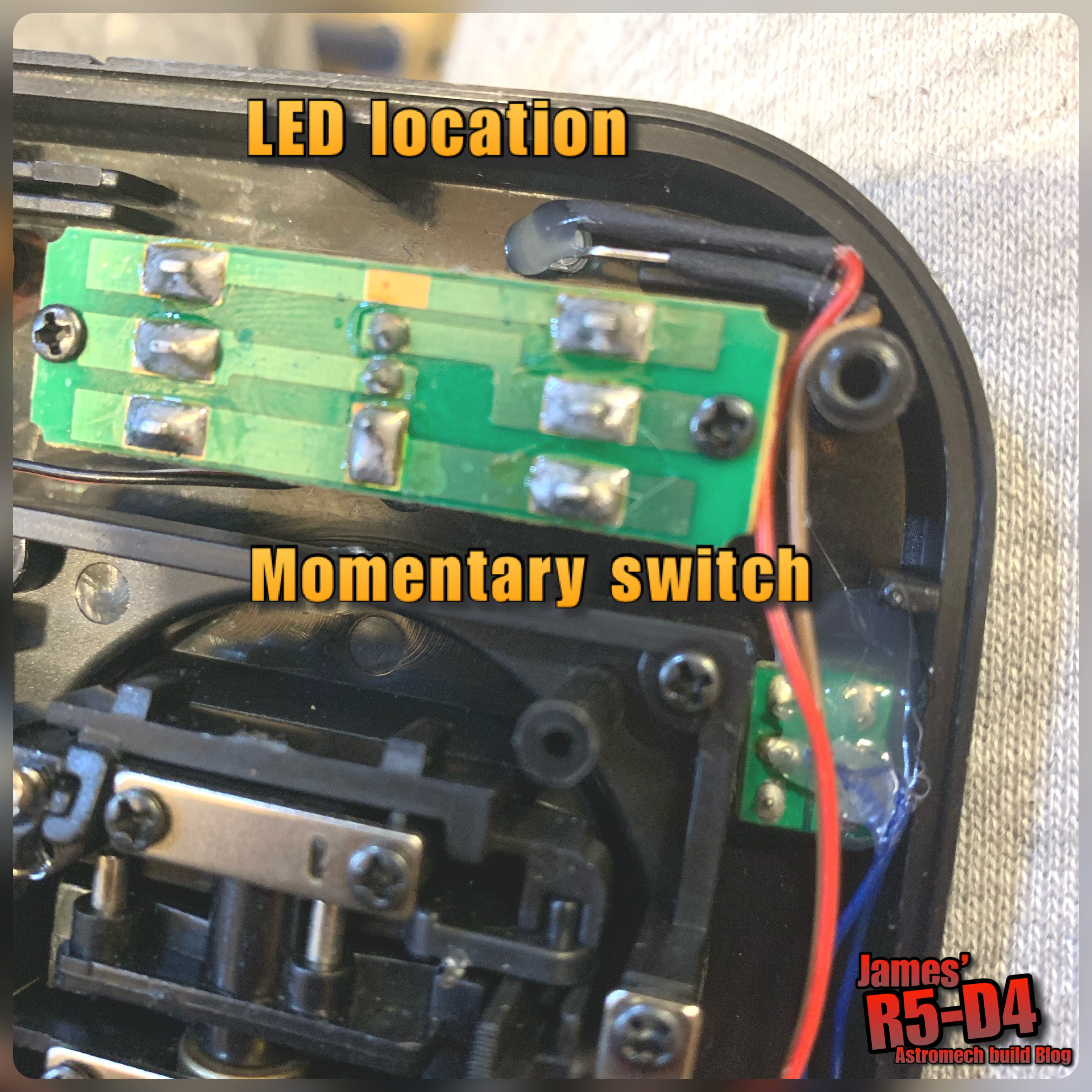
So after some thought and tinkering, I found a momentary switch and tested it on the remotes contacts to check that a remote switch WOULD still work lol. Two dabs of solder onto the contacts and the remotes remote switch was on. Next up was the LED, again, having it show that I HAD actually pressed the button, I wanted an indicator. A quick test with the contacts of an LED onto the contacts of the board mounted on, showed that it lit up. Two more dabs of solder and we were in business.

I positioned the LED next to the Utility arm's switch. Both these were secured in place with hot glue.

Above picture: the switch is just below it. The momentary switch was positioned a bit further down due to space, but it's still in a good place to press, without loosening your grip on the transmitter.

Front view of LED and new momentary switch.

Then came the really tricky part lol, finding a position to locate the actual remote's board. I covered exposed contacts with electrical tape, before placing the remote's board inside. I then applied more tape over it to secure it. I did think of securing with hot glue but decided not to.

Just need to test it next....

Yep, it lights up lol.

March 20, 2022

R5’s Bad Motivator : reincarnation

After months (years) of saying I must get R5’s mojo back, I’ve made a start on getting his motivator system back up and running. Well done James, given myself a week to get it ready for next Saturday’s event at NEC Birmingham 😂😂😂 MegaCON Live.

See previous posts about the issues with the car door actuator failing and then upgrading to the magnetic version.

I dug out the parts bags and laid them out on the bench. There’s half still in the dome, the actual pump to be used….and also the vape tank….

In the above picture, there’s two air pumps, one has a broken terminal, so is salvage at the moment. The magnetic solenoid (left, wrapped in blue) is attached to the pivot arm, the clear plastic bag has some mini voltage regulators, the white board is the original one I used, the orange block below it is the time unit, below that is the new remote control unit, and finally the activation remote control wrist strap (bagged up on the right).

R5-D4's Bad Motivator system 2021 - Part 1.3

June 2021
Decided (last month May) that I was going to be the start of getting R5's
'Bad Motivator'
…….back installed again.

It all started waaaaay back in 2019 (part 1.0)........


....the door actuator needed replacing...... again!

The following past Blog links:
The design's were all from my early days of 3D designing components, so they needed some slight modifications and alterations for printing on my Tevo printer.

This new idea is to combine all the components onto the one assembly bracket, which is secured to the inside of the dome.

The solenoid holder needed a few changes, but the knowledge I have gained meant that the design itself was sound.

The bracket which supports the motivator and rail, had a notch in it from an earlier design. This I could use as a location point for the solenoid support bracket.

One thing I did have to change was the pivot position on the bracket arm. The solenoid activates in the pull position when powered on.
*****************************

The electricals needed re-doing as I will also be replacing the original 4 channel remote control with a two channel one.
This will operate the original Bad Motivator pop actuation, smoke/vape system....... and new for 2021.... (if all goes well)..... an amplifier/speaker/sound card to play the sound effects!

…..March 2022, thought I had posted this up last year 😂

November 10, 2021

Trading Card Dispenser - in action!

 
I’ve had a few messages asking about my Trading Card Dispenser and how reliable it is. 99% it’s flawless, you just need to pre-test it once you’ve loaded your cards in. I found that the cards sometimes stick, but pressing the activation button (on your remote control) a second time, usually gets the card to fully eject.

You also don’t have to worry about dispensing another card as the wheel drive isn’t in contact with the next one until the previous card has been fully removed.
Hence why you can re-press the button if one card gets stuck.

I was able to test out the TCD and R5’s utility arm for the first time back in July, with the assistance of Giles to ensure a card was dispensed lol :D at the MOT event.


Click on the picture above for link to my short YouTube Channel video.

Components and parts list available on my Thingiverse page

I've since been working on an updated version......

May 18, 2021

Remote control/wristband 'communication devices'

Finished these both off with Velcro attached to the straps.

Half hours worth of stitching by hand, sees both surfaces of the Velcro attached.

Am really please with how these have turned out. Of course how useful they actually are will be found out when they are actually used :D

Software used:
AutoCAD Inventor 3D [work program]
Astroprint [online slicing program]

*** UPDATE OCTOBER 2022 ***
The stl files are now available free on my Prusa account.
Blog link here.

May 04, 2021

Remote/wristband 'communication devices'

A while back I posted up that I had designed a clip mount remote control fob holder for R5’s ‘Bad Motivator’.
The idea being that it could be glued/Velcro’d to the transmitters rear, allowing hand’s free’ish control of the remote.

Well with all the new 3D models I’ve been drawing up, one of them was a version of a communication wristband from Solo.

The purpose of this was purely as a costume prop, but I soon realised that it could actually be of use as a remote control wristband holder.

So I started changing design dimensions to suit the stripped down remotes internals and the first 3D printed version came out great!
(I just need to design a front cover/panel for the buttons)
This version, above, has had a few more alterations, like a retaining lip and also a location for a Brass insert to be fitted to secure the front panel.

Next was to modify this second design version to suit the other remotes. This version I also drew up the cover/panel at the same time as the wristband.

And here it is......version 1....
The two holes on raised pads are for screws to secure the front panel on, via brass inserts.

I did some more alterations to accommodate the four button remote control I have. This version required the cover/panel to be more raised as this remote has raised, tactile switches, compared to the low profile, metal contacts of the above version circuit board. To combine the fitting of the cover/panel, the main wrist holder, now has a 'lip' for the panel to slid under. This helps secure the front better and requires only 1 screw.

The above picture shows them pre retaining lip and retaining screws.

The four button remote has been the hardest to get right. I've gone through more test prints on this version than any of the others.

I've also increased the 'shell' thickness to hopefully increase the strength of the wrist strap slots.
The 3D printing with increased shell thickness and a new curved strap slot, have made them stronger.
I’ve posted up a short video on my YouTube channel. Click the picture below to view link:

I’ve ordered some Velcro (as I couldn’t find my stash), this will be for the straps.

June 05, 2020

Remote control holder - 3D printed

Whilst drawing up stuff, I thought I'd draw up a clip in holder for my mini remote control(s).
The idea being that rather that have it loose or stuck to the transmitter, the holder could be fixed and the remote could then be removed for battery access.

I drew version 1 up and got it printed off.

remote control holderremote controllers

It didn't come out to bad, see picture below.
A lip I thought it would need, that fits through the key ring hole, well it didn't, so filed it off.
3D printed remote control holder
Version 2 has a few other slight changes. These I can show when it has been printed.

Once happy with it, I'll add it to the other files on my Thingiverse page.

March 03, 2020

Weekend work on R5 - TCD ,‘Trading Card Dispenser’ control box fitment

Last week I drew up a curved back, bracket to mount the trading card dispenser control box onto. I wanted its position to be closer to the TCD, ‘Trading Card Dispenser’, itself. The power distribution terminal blocks position had to be moved as the leads had already been connected. Still, it’s better as the 12 volt cables don’t have to reach as far round to the distribution block.

The main 12 volt cables still need to be connected up to the distribution block. The other pair of cables seen are to the dome motor, but require the speed controller to be fitted inline.

February 05, 2020

Another mini project 2.2 - Trade Card Dispenser fitted

At the weekend I test fitted the TCD and it's control box, into R5.
As the card dispenser is going to be central, positioning it wasn’t very hard. The control box, for now, was just positioned in a suitable location lower down on the frames woodwork.

This picture shows the dispensers position behind the Utility arm, in it's closed position, to show clearance of it.
Trading Card Dispenser

View through the arm opening
Trading Card Dispenser

Cards protrusion from utility arm opening.
Trading Card Dispenser

 Card protrusion from utility arm outlet.
Trading Card Dispenser

Control box, temp position.
Trading Card Dispenser

Next up is sorting out the rest of the electrical's and activation of the Utility arms again.

January 25, 2020

Another mini project 1.9 - Trading Card Dispenser

Yesterday I uploaded the stl files and the assembly instructions to the UK builders club forum.
The components take a while to arrive so it will be a few weeks before I get any feedback. But as I’ve printed the same version, there shouldn’t be any problems lol.

The other fun part was creating instructions for 3D printing (orientation & support placement), assembly of the bought components and then fully assembling of the unit itself.
Created a PDF to be downloadable with simple instructions.

I finished printing my frame holder to fit into R5 so hoping to get this all installed and tested soon. There’s still work to be done with alignment etc, so more posts on this to come.

January 23, 2020

Another mini project 1.8 - 'Trading Card Dispenser'

So after a bit more fine tuning,
the TCD is now complete.


The TCD..... The 'Trading Card Dispenser'

I was still waiting for an electronic component to arrive in order to wire everything up to test it. It arrived and it wasn't what I was hoping for, so I'll have to revert back to my original electronics setup, not a big deal as this doesn't effect the actual dispenser being assembled or operated.

I've designed this as a self contained unit with it's own remote controller & timer delay off circuit, but it would also be able to be controlled via any momentary switch, Arduino etc. I'm not an Arduino guy, but from what I know this is possible.
The motor runs on 6v and would only need to run for a few seconds.

The unit comes in 4 parts, base (in red), plate (in blue), lid (in green) & a wheel adapter which fits onto the motor. (colour's are for identification only, not actual)

There are then 4 components required to be bought in order to fit and glue together to fully assemble. I'll post up this list and an assembly instruction PDF when files are released.

More updates soon.......

November 28, 2019

Another mini project 1.3 - ‘Trading Card Dispenser’

So I have now named this project 'TCD' lol.

Monday I started to design up a 'box' to put the electronics in for ease. This was drawn up in AutoCAD Inventor. In my last post regarding switch relays, it had given me an idea on how this could also apply to this project.

'switch' - update:
I printed a lower plate that the switch could fit into. I wired a switch to activate an LED when the pressure was released.But the pressure required to keep the switch down wasn't achievable, so I'll have to think of another position to locate a switch.
TCD project

Back to the electronics box:
After a few redesigns and only a few actual test 3D prints, I'm really happy with the finished box. Here's my instagram post picture.
TCD project, electronics box, 3d printed
Really please that the two clips I designed actually work [on my second test print lol]. It's the fine tuning of the sizes, plus here, minus there so that the tolerances fit when they come together.

Ultimaker Cura image on the printer plate
TCD project - Ultimaker Cura


And here's the soldering up of the components that will fit inside it.
TCD projects, electronics
This version is for my first attempt, but this could be customised to by controlled by other methods. In the above picture, you have the 'remote control' [bottom left], a 'timer relay' [top orange box] and a 'micro voltage regulator' [right]. Not shown in this picture will be an LED to indicate power. At some point I want to fit another [probably a remote LED] to indicate via the micro switch.

December 07, 2018

Smoke system tutorial - Part 2.2 (on hold)

Carrying on from my first post back earlier this year,
part two is to do with the remote
control/power side of the unit.

R5's bad motivator system
Smoke system set up at present, soon to be upgraded.

I was going to write this all up,
but am now working on another upgrade...
so will post this ALL at once I've tested it all and it works.