Showing posts with label WED-15 droid. Show all posts

November 25, 2025

Treadwell WED-15 .......the Rise of the Machine..... Part 29

Post started 4th September 2025 - into October.

Treadwell has taken a back seat for a while now, but I wanted to finish building him before our annual builders Christmas meet-up, so with renewed energy.

Treadwell Droid - WED-15-77


List of things to do is always a good start:

    1. New idler axles                x 6 off👍
        New drive axles                x 2 off👍
    2. New correct Wheel spacers x 6 off👍
    3. New motors                     x 2 off......................??? 👈
    4. Signal booster fix. 👈
    5. Mast box build - 3D printed parts etc. - click here to see Box Build Post.   
    6. Remove the original guide wedges from the tracks.👍
    7. 3D print more new round track guides. 👍
    8. Remove the paint from the drive wheels [sticky]👍
    9. New front 'tension' blocks. 👈
    10. Unexpected track repair......... but then a WIN!!! 👈
    11. Volume knob. 👈
    12. Fake antenna UPGRADE. 👍
    13. LED's fitting to 'eyes'.
    14. Constraining the ‘eyes’ to each other.

1. Starting with....new axles:
I bought an 8mm dia rod months back, but it was slightly over size so needed turning down on the lathe in work, to fit through the bearings etc.
First one turned out good [turned.....machined.....see what I did there 😂]. Only having lunchtimes to do this, drill a centre hole to then use a revolving centre so as to be able to machine the full length of the spindles. Next is to then thread the ends for the flanged M8 Nylock nuts.
axles, treadwell droid, wed-15

I also needed to machine up two new longer drive axles, to allow for the wheel spacers. These are 10mm diameter, stepped down to 6mm dia for the shaft coupler. No reason really for the 10mm dia size, except that this was going to be the size for all the axles.


2. Wheel spacers:
On closer inspection of the alternative WED base droid, seen in Mos Eisley ally way, WED-9-M1 (Star Wars Fandom), you see that the tracks are spaced away from the body!
WED-9-M1 DROID
WED-9-M1 DROID

So I had drawn up and 3D print off spacers, to match. Not sure how, but I got the diameter different, so had to reprint these. Not sure yet if these will be free rotating or if I will glue them to the wheels.
Pic from July 2024:
3D printing, track guide, treadwell droid, wheel

3.New Motors:
A possibility......???
My thoughts were that perhaps they wouldn't be up to the power needed. Even though testing proved they are.

4. Signal boosters:
I found that when WED was fully assembled, I was having problems with controlling his arm and head. One possibility was that the battery was low. The second was that [with my first time sending a signal over this long length of cable] the signal was too weak. So I bought two sets of boosters fly-leads to try 👍.
servo signal booster

5. Mast box build:
I had already drawn up plans for this when I designed the head box. See independent post for more details.

6 & 7 Track guide wedges - DELETED:
The 'screen accurate' guide wedges, were unfortunately too stiff for the tracks, and weren't flexible enough. So had to remove them and replace them with the new 3D printed round track guides [POINT 7].

7. Track guides:
I tried a few different variables, one being a slightly tapered diameter, after my original 'cannon' style didn't work, I decided to try this [credit goes to Paul's Bots]. Link to Paul's tread/wheels build.
I need to narrow the wheels channel for better location of the guides. So more 3D CAD/printing required.

UPDATE: 16.9.25
The new inner wheel guides printed great on version 2. These were slightly modified for structural strength and because visually they don't need to have the slits in like the wheels themselves.
After testing, I will update the 3D wheel models to incorporate this addition.

Here are the new wheel inner track guides, in black, glued in.
3D printing, track guide, treadwell droid, wheel
idle wheel with inner track guides

Test first guide popped into place on the track.
3D printing, track guide, treadwell droid 
3D printing, track guide, treadwell droid
As with Paul, I made a 3D printed drill template so that the holes would all be central on the track. I did have to modify mine from the one I created from my moulds as the teeth sizes were slightly narrower.
So a total of 140 were printed off. 80 off each for every other groove.

8. Drive wheels paint removal:
The paint reacted with the curing rubber had became sticky, sticking to the tracks. So using sand paper, I removed the thick paint from the outer diameter faces.

9. Front 'tension' blocks:
The axles for the two front wheels were long enough, so I just altered the [3D printed] inside face that has the nut recess, so that a Nylock nut can secure the axles in place.
The location on the base has to be repositioned as the original tracks were a bit too long, requiring some woodworking alterations.

10. Track repair/replacement:
It wasn't on my original list of things to do, but on removing one or two of the 'track guide wedges', on an early join [one NOT overlapping] the joint broke. So I ordered some more rubber mix, but repair work will be put on hold as....... 👇👇👇

New Tracks:

11.Sept.2025
I thought I'd have another search inline for the tracks [super-charger timing belts] and found some here in the UK [at last]. Decided to bite the bullet and purchase a pair.
Bolton Engineering, treadwell droid, rubber tracks

Click picture for link to Bolton Engineering Products.
Bolton Engineering
I have no affiliation with this company, am linking for future builders.

The calculated cost of me making my own tracks was over £100 in total, not including the time to design up and 3D print off the moulds etc. The fact that they are also NOT internally web meshed, didn't fill me with confidence on they're lasting performance. They would still be ok for 'display' purposes.

UPDATE: 16.9.25
Belts arrived and I couldn't be more happier 😊😊😊😊😊
It may sound strange, but there are certain things that, for reliability, need to be sound. The fact that Tread needs the tracks to be 100% dependable/straight/strong, means that driving him with confidence is now a guarantee.

11. Volume Knob:
Still not as loud as R5, plus it does need to have a noise suppressor fitted. So whilst searching for ideas, I found this for drone fpv video feed interference suppression.
I fitted it, after some testing to find the cause, inline with the mini 'step down voltage regulator.'
electronics, 3D printing, noise suppressor

And of course, I had to CAD up a bracket for it to be mounted onto the control board. The volume still isn't up to the loudness of R5......

12. Fake Antenna base:    [6.10.25]
I wasn't really happy with the fact that the fake rear antenna, was made out of a steel piece of bar, no flexibility and defo safety concerns lol.
So drew up an adaptor in TPU that fits between the two parts as a test. This then fits onto the original base part. The upper section is also now a found piece of leftover carbon tube.

13. LED's fitting to 'eyes':    [8.10.25]
This had been on my to-do list to bring some 'life' to Tread. Recently got hold of some large blue bulbs and sockets for them off eBay. Drew up a holder in CAD and 3D printed off some test versions, figuring out along the way how best to install them.

Originally it was going to be on the inside base of the head units.
Idea no2 was to mount the LED brackets to the rear of the lens window frames.
Treadwell droid, WED-15, LED's, 3D printing

Treadwell droid, WED-15, LED's


Tested the LED bulb behind the acrylic and it looks good, but needs to be diffused more????

14. Constraining the ‘Eyes’: (16.10.25)
The single-servo’d ‘Eye’, wasn’t very well linked/connected to the other. This bugged me!
So I needed a better way to constrain its movements.

I came up with the idea of installing the geared parts from a broken servo, into the unservo’d housing. So I re-designed the fake piston and connected both servo horn arms to it. Making the second ‘eye’ constrained with the servo controlled one.

UPDATE POST WITH picture(s)..........

Almost the end of November, and still have a few last things to get ready before the annual Droid Builders Christmas get-together....

A weekend blitz on the to-do list including the mast box build, and the final piece was to open up the slot for the front wheel axle, and some new location plate holes.
Treadwell droid, rubber tracks

All (99%) complete, ready for next Saturday…… display and testing lol.

This Build has reached 29 stages, so to round off, I'll post one last Blog update with loads of photos lol, to make it a nice round 30.

#treadwelldroid #droidbuilders #rebeldroidsnet #3dprinting

October 17, 2024

Treadwell WED-15-77: mast box build (not yet made)


March/April 2024
With the tracks completed
(at the time of writing this), and after making the head box, I needed a storage/transport box for the ‘mast’ section.

This was going to be built using the same design as the head box. I 3D printed the corner pieces again and then modified a copied version into a middle section.

I bought some more carbon fibre wrap and plastic edging.

October 2024: this still hasn't been built yet.

August 09, 2024

FunkoPOP Treadwell Droid WED-15 (Version 3C)

So here he is, version 3B, version 3C

As I mentioned in the last post, version 3, had been modified so that the claw end was supported once printed. I also added some other small details, because I wanted to lol , the pincer utility arm was added and more de-find (hence the B now C designation).

So this was version 2 below :

Version 2: main claw arm supported by mast at bottom.

Comparing original Version 1 (left) with Version 2 (right)

Here is the 3D render of version 3CPicture below.

Didn't get round to painting him, but this is how he would look.

I've uploaded this version to my Prusa page, so check it out.

July 18, 2024

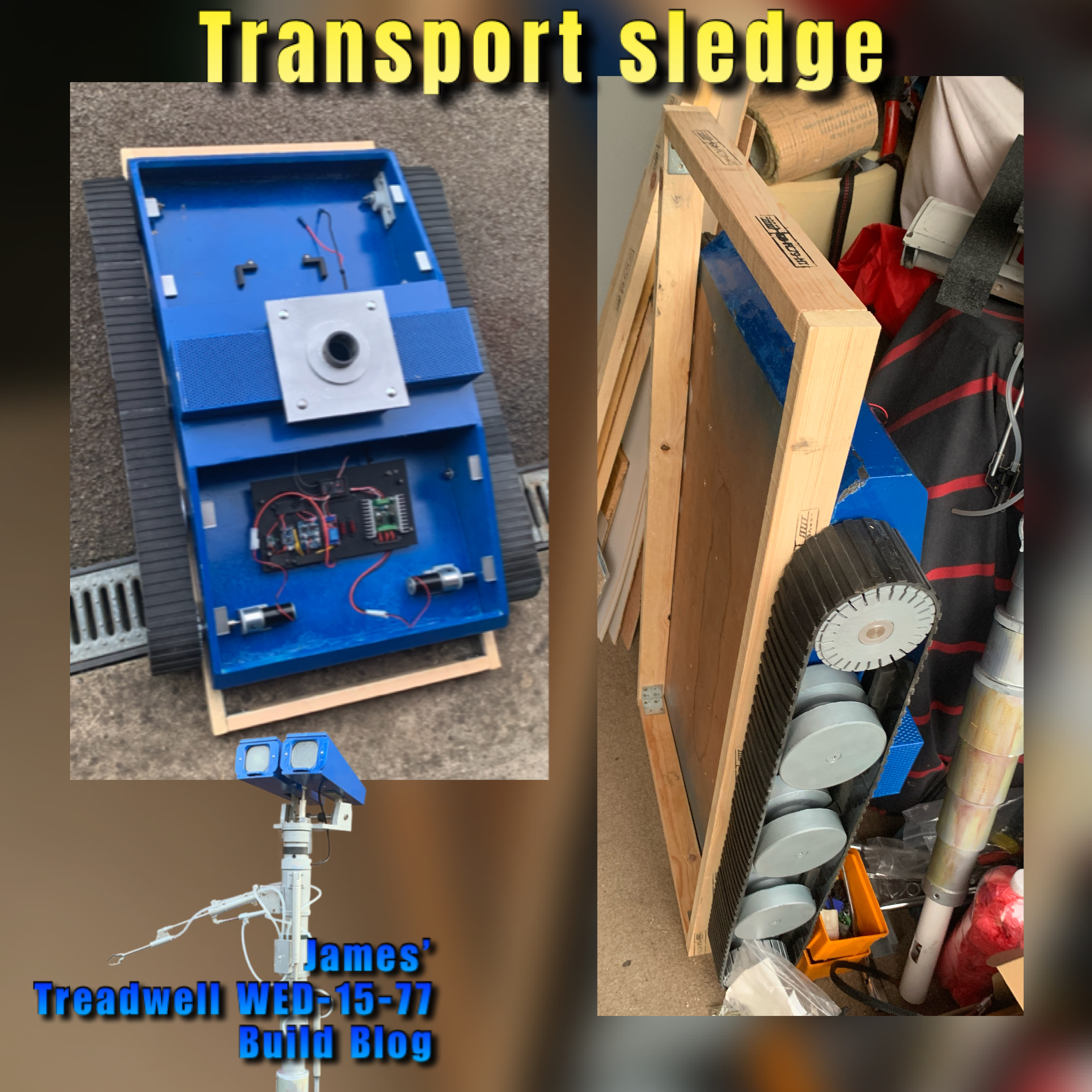
Treadwell WED-15-77: transport sledge (part 2)

Wrote this the week before the Mshed event.....

The bottom edge needed strengthening supports, so added two angular sides pieces.

The foam i had from work was cable tied on in place. A top one will also be fitted, more for protection when the whole unit is on the roof bars.

I needed to add some securing straps to keep WED on the sledge.

I added some wheels for easier movement and obviously a handle.

For protection and to look better lol, I needed to paint the sledge, so after a light sanding, primer coat, I finished it off with the same Blue paint I used for WED. I was going to go with Black, but changed my mind lol.
This is the only picture I have, from painting and at all lol. Must do better 😂

July 11, 2024

FunkoPOP Treadwell Droid WED-15

It had to be done lol.

I drew up WED-15 as a FunkoPOP figure.
Version 1 in Cura, printed to see if it worked.

The arm broke off when removing the support.

First time using tree support setting.

I had already started working on version 1, sanding, filler, spraying it up, whilst modifying the model in CAD.

After primer had dried, I masked off the body and head so I could spray parts silver. Next two pics.


Then it was masking off the silver parts and tracks, to spray body and head blue.

Reveals the painting.

Finishing touches, black track, silver wheels, a bit of weathering.

Version 2 was slightly modified, but not printed.
Version 3 will be the final version. It has the location holes in base, the claw arm has been repositioned so that it is supported by lower mast diameter.

June 08, 2024

Treadwell WED-15-77: transport sledge (part 1)


So I’m going to need something for WED-15 to transported on safely. Not just at events but to them as well lol.

This is going to combine the two needs, hopefully, in one.

The idea is that the WED sits on the sledge and has restraints and wheels, this takes the strain off the tracks.


Then the sledge itself has location points so that it can be safely secured to my cars roof bars.


I picked up some straps, unfortunately not in blue lol.

The sledge also has padding planned on both ends to protect the base ends of WED and be painted as well…… TBD.

May 24, 2024

Treadwell WED-15-77: Part 27 - Testing


Well…… A few hiccups before the finale.
  • The tracks need shortening (both).
  • The mast base support needed a slot in it (think i did this as a second version on the model but didn’t reprint it.
May 9th
Connected up the battery and plugged in the fuses and plugs into the receiver, and powered up.
After dipping the Sabertooth into tank mode, right transmitter stick in full control.

I added WED-15 to the transmitter, and colour coded the LED’s to match.

Might also have to invest in some blue sticks.

May 10th
Today was the mast and head install.
This was there I realised I hadn’t but a slot in the mast base plate for the servo leads. I decided NOT to bother with the servo block plug, as it would of been difficult to reach once the mast was fitted. I just extended the servo leads.

I first connected up the head pivot servo.
Then the eye/head servo for the up down action.

Once happy with this, I connected up the main claw arm lift servo to a switch on the transmitter. Again, all good.
Next was the claw servo…. It worked but not for long??

Its been a while since testing it so don’t know if I hadn’t done something right, as on closer inspection, the case looked warped.

Took it out of the forward servo casing and, yes, the gears had jammed and one had melted, over heating the motor and melting the servos housing.

I did take a test video, you can watch it in the next post.

May 13
I trimmed the neck servo to increase it’s turning range. I also adjusted the head servo to increase it’s looking up position.

May 15
I got round to pinning the head/eye supports to the pivot bar. I had to fit an additional cross bar back in, for rigidity.
The ‘piston’ and the two ‘clamp’ rings got a respray, to a more brass look.


The eye/head servo lead I decided to modify by adding an additional plug on the outside of the neck. This allows the eye/head unit to be fully removable, found it so much easier to work on this way.


Added a spacer to reduce the clearance between the neck and mounting plate.
This fits under the bearing shim.


May 21st:
Tested out the track on the ground.


It works, but the teeth are still a problem, also the front brackets are flexing under the tension and there’s not enough torque on the axle nuts.
3D printing some beefier versions out of ABS.
I’ll also be printing new motor brackets in ABS too as these were flexing slightly.
Ordered a new nano servo.

March 16, 2024

Futaba: vintage M - series transmitter

With building WED-15, I often refer back to photos and even videos from the original behind the scenes. One thing that is always in my mind is the transmitter, a Futaba M-series transmitter, which were not only used for WED-15 but also for R5-D4.
John Stears - on the Star Wars set,
controlling the WED droid

I was fortunate enough to get a dual purchase of a 4 channel and a 6 channel, transmitters, a few years back (2016). Neither came with an antenna, but I was again lucky enough to find one, on eBay, for my display setup.
Futaba M-4 transmitter

Link to Blog post(s):
Post - ribbon indicator part 2

I keep a search update on eBay, for similar transmitters as well as antennas, which always seem to be missing. Over the last few years the price of these transmitters has increased significantly!

I’ll be updating my display information to include the WED-15 image of John Stears.

March 09, 2024

Treadwell WED-15-77: Part 25

 March 2024

I started this build back in November 2021:
Link to part 1 and now it’s coming to be completed this year 2024.

I will be creating a page viewable via the top tabs (PC) or via the drop down menu on your phones which will have links and photos to these posts.

This month:
  • Spray Painting
  • 3D printing
  • Rubber track moulding (YouTube)
  • Re-assembling
  • Electrical installation and testing
Painting the base:
I stripped the base of everything not made of wood lol, a pain, but it means I don't have extra weight and also I don't have to worry about something getting knocked by accident.
I then masked off the paint I wanted to keep and sprayed the bare wood with primer.

Some of the area's not sprayed are because these are going to have panels covering them, as painting neatly wouldn't of been easy. Here’s the masked off areas, spray primer work.


Once happy with the primer, I applied the blue paint.

A clear coat was going to be applied once dried, but the order didn't arrive, so this will have to be done at a later date.

Painting extras:
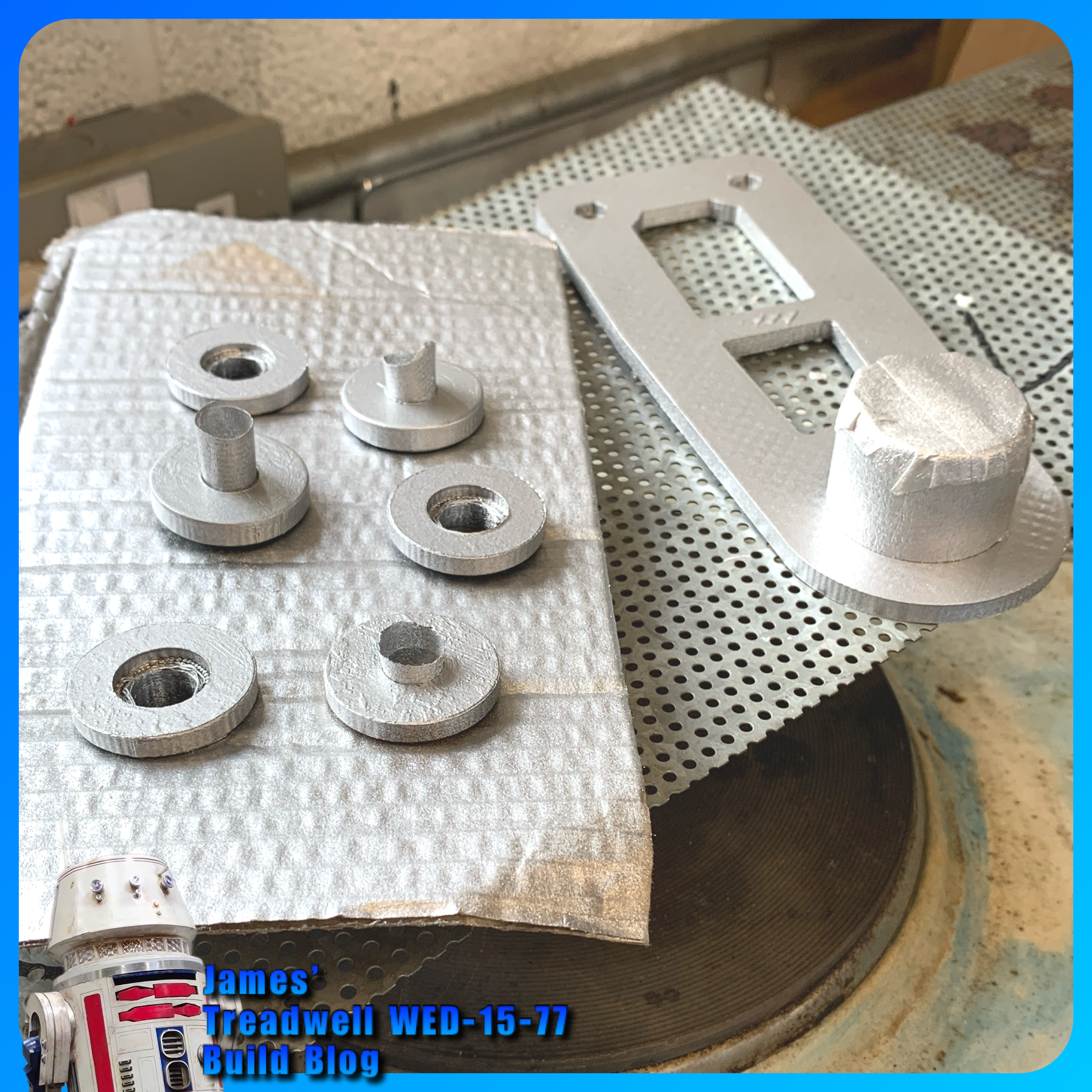
The one remaining wheel, plus the front wheel brackets and the lid supports, all got a coat of silver (not Plasti-kote) paint.


Also sprayed up were these missed wheel bushes and the mast base support.


Servo connections: block plug or just loose.
(Planned work, now next month’s schedule)

Tracks:
Ordered a single batch of two part mix of the mould mixture, to create the tracks with. I thought, if I need more, I can buy more.
The new track mould I printed last month didn’t print out very good (lifted off bed so not flat). Later, after a few failed prints, I found that the nozzle wasn’t as clean inside as I had thought, even with hot and cold pulls. So I didn’t reprint it as I already had two moulds anyway.

I used my original moulds (green filament) ones. Dusted with talcum powder as a release agent. I had seen this done, but don't think it works too well in this application lol. Read on for what I eventually used.

Here are the track moulding in progress. I made a video of this now up on my YouTube channel.

In the video, the track that couldn’t come out of the end of the mould was due to the filament that didn’t have support and had sagged, so the fluid mix was absorbed into it, bonding it together.

This part of the mould has been removed (cut out) and sealed with superglue.
Only one of the two mouldings poured, cured, bit disappointing really and don’t know why?? = after a few more attempts, I figured out that the mixture wasn't mixed properly and so hadn't cured properly.

Here is the joining plate with two ends, of already moulded track in position. Mixing up and pouring into this, joining plate, joins these together.

The poured join. Inside doesn't look great, but that's not important.

This was another poured moulded section.

Here is all the track made so far, these will all be joined when the second delivery of mix arrives.

The mixing and moulding process improved as I went along. I now have enough moulded to complete one full set of tracks, but will have to order a second batch of mixture.

Guide teeth:
I did have a go at moulding a ‘guide tooth’ onto a piece of track.
This first attempt, didn't work. The rubber didn't bond to the back of the track like it does with the joining sections, as I had expected. Once released from it's mould, the thickness (height) effected it's ability to flex with the thinner track when moving over (around) the drive wheels at both ends. So am going to have to look at something else or another mould idea.

Glue:
I did find and test out some special loctite glue which can be used on rubber.

This seems to work, still testing, but this could be what I need.

Mould Release:
Here’s the mould release agent I used, found a can in work:

The following picture was the last of the mix I had to bond together two pieces of the track. The rest went into one and a half track mould.

Video of the track coming out of the mould on my YouTube channel.

Test laying the track on the wheels:


Re-assembly:
As the build progressed, little snags appeared. One being my choice to use nylock nuts and washers to secure the front wheel brackets. The protrusion restricted the required clearance and they would catch on the inside face of the wheel.

Plus i needed to trim the bolts down in length, and use normal nuts with thread lock.

Not to waste the nylock’s, these were swapped over on the mast base support bracket.

Electrical:
I needed to move the power switch to the outside panel for ease access. This meant unsoldering the switch on the panel, adding a new plug connection and fitting the switch into its new location.

I drilled a dia 20 hole and fitted the switch just behind the mesh panel.

I finished off adding the power cable from the battery to the board, via the switch. And (test) connected up to the battery……

…..we have lights on the components.

Will the next Blog post be the final one…..????