Showing posts with label Voltage regulator. Show all posts

September 14, 2022

Servo Tester + voltage regulator…..box

Not like I don’t already have enough to do, I decided I wanted a housing for my servo tester and it’s voltage regulator. I’ve had these connected up for years now, but really wanted to have them in something.

I use it on my 12v work bench power supply, but also with a mini 12v battery when at events etc.

So after measuring the two up and after three test prints, I finally (99%) completed this enclosure. I even added a button for the micro switch.

The latest version (not in the pictures) has the servo identification icons on it [s+-] for correct orientation for the plugs.

This is the version that’s up on my Prusa account.


Click on the above link for the files 😎👍🏽

November 20, 2021

3D printing: SD card Sound board holder

 So i needed brackets/holders for the components for GOUD-4’s sound system.

Some i found on Thingiverse:
  • The amp bracket
  • The voltage regulator bracket
….the others I had already drawn up, like the mini voltage regulator. Next up tho was a bracket for the SD Sound board card reader. This is the now discontinued Sparkfun model that’s continued unbranded, to be produced and sold on eBay.


It took about four attempts and designing the bracket to both enclose, support and be a good secure fit for the board. I made a cut out in the rear to help with pin identification. There’s a lip on one end that the board clips under to ensure it doesn’t come out.


October 05, 2020

Teeces LED work for Mike's dome [August 2020]

27th August 2020


     A few weeks back I was asked to help wire up a set of Teeces LED light and add some LED's to illuminate the Holo Projectors x3.

R2 type dome getting some lights fitted

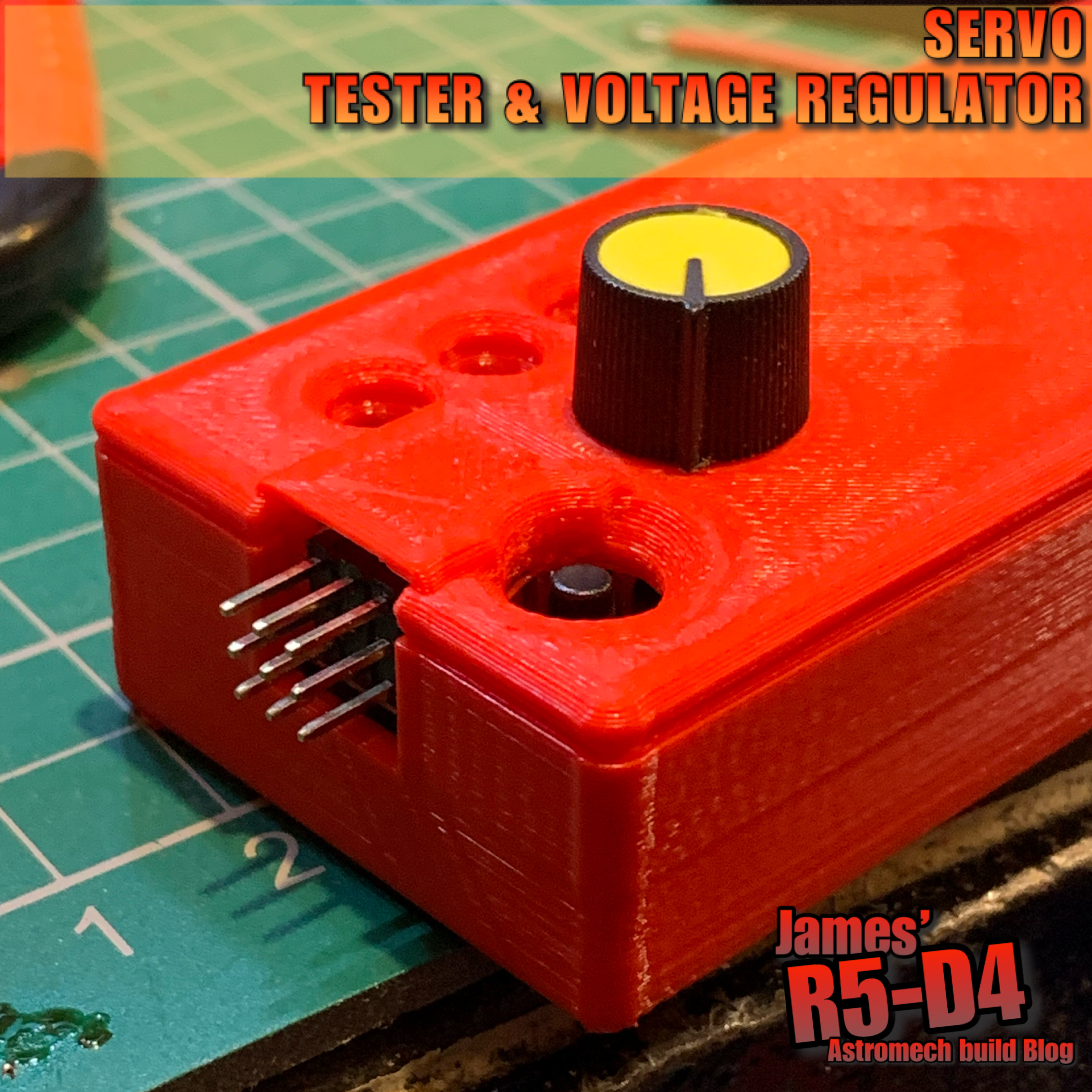
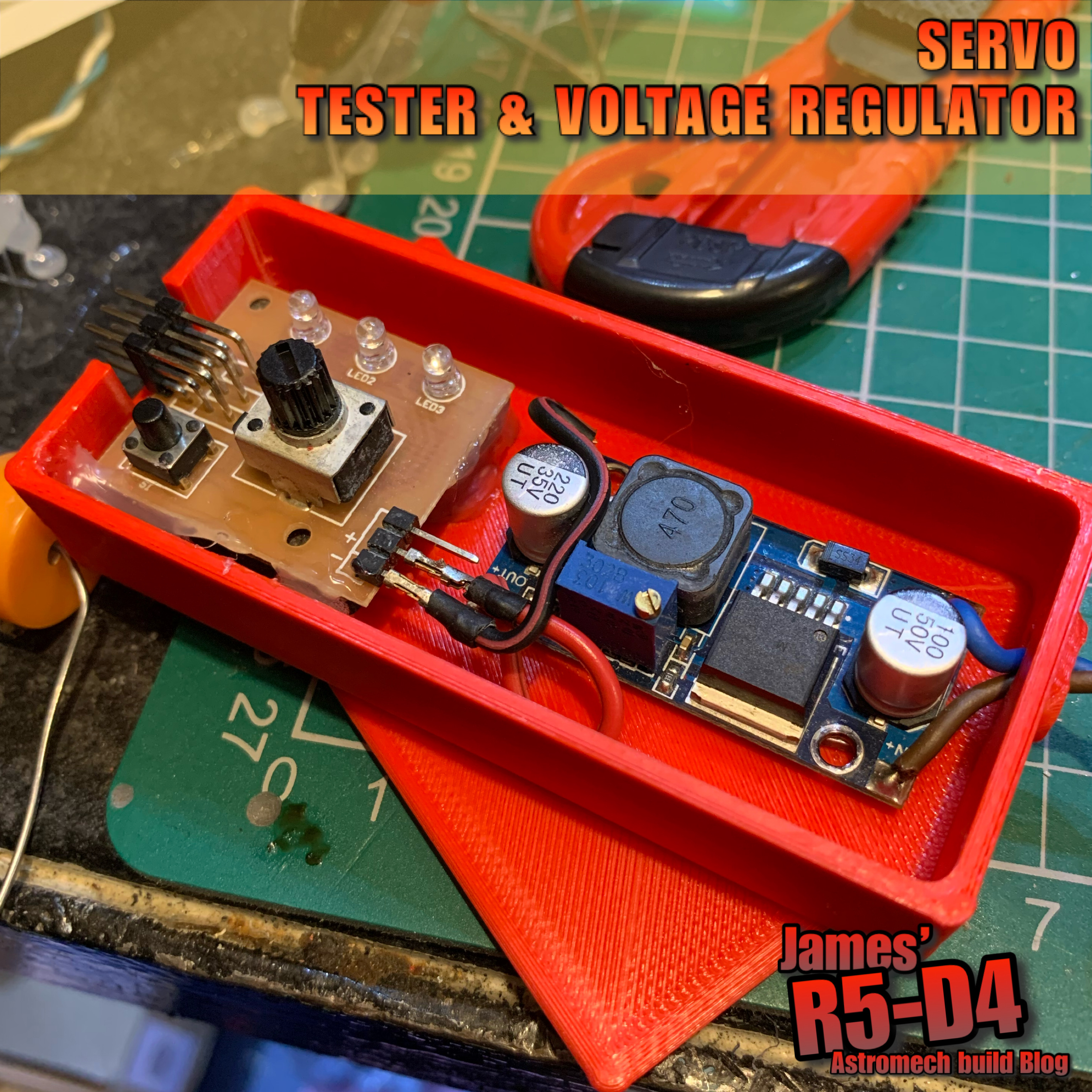
I fitted a voltage regulator to drop the volts down to 5v.

Teeces lights lite up
These are the main lights for the dome illumination.

Mike also supplied some torch LED panels, which I managed to solder up wire connections to after figuring out why they all didn't light up with just one ground wire connected.
Torch LED units

After soldering these up, I had a thought about how to fit these into the Holo Projectors, without the dreaded 'Holo wire twist & break'. So I dug out my Holo Light units I made years back for my R4-D4 dome.

I did some updates to the LED holder, now that the 3D printer is better than the previous one lol and also upgraded the bearing holder.

Holo Projector LED holder

The bearing holder, is designed to be shaped with a file to be a tight fit into the rear opening of the Holo Projectors eye. The whole unit acts as a slip-ring arrangement, allowing the LED's to be connected and lite, but also allowing the Holo Projector to fully 360 degree free movement, without worry of 'Holo wire twist & break'!

Short video demo of new holo slip-ring

No more 'Holo wire twist & break'

Mike's dome only has two moving Holo Projector's, so these received these units. The third Holo is static. Nect up was installing them into his dome.

Panoramic view of inside the dome - LED's

Next up is to finish installing the power cables, the Teeces units & connecting up the power switches.......

wiring up the switcheswiring up the switches

And some pics of LED's illuminated.

illuminated LED'silluminated LED's

illuminated LED's from the inside of the domeilluminated LED's

Mike was kind enough to make this new tool storage box sticker, nothing wrong with the original lol, but hay....everyone should have their name on their tool box.

tool box stickertool box sticker


Interested in sign's etc, check out his website...

Click this link to his website ->>> Vinyl Designs

May 14, 2020

Sounds for droids 2020 - upgrade 1.4

After the last testing and the feedback created being a nightmare and the ground loop isolater circuit just wasn't doing anything. So rather then using standard speaker wires, as can be seen in the video in my last post, I cut down the leads from the RCA leads and swapped the standard cable over for these.

OTHER WORK
Since then I've been working on creating 3D printable enclosures to house all the pieces.
Sorting out the orientations of them so will post up once done.


.......3D printed parts for the utility arms have been done
by a work college and are now in the post to me.
Thanks Will.

April 28, 2020

Sounds for droids 2020 - upgrade 1.3

Saturday I got round to playing with the sound board & set everything up to test out the new amp.

Rewind a week to the issues I had trying to upload the sounds to the board. I had just grabbed a usb cable I thought I had used before to connect the board to the laptop, but it wouldn’t connect???
After numerous attempts and system checks, I realised the cable was a power one not a power/signal one. Swapped cables and instantly problems solved lol.

After testing the sounds using my phone, i needed to actually test with the sound board. So after some wire soldering/connections, the board, amp, speakers where connected. I had ordered a potentiometer as a volume control, but it still hasn’t come, so I dug out a broken large servo and used the pot out of it. Quick YouTube/internet search, and it was soldered up according.
This might look like a mess lol, but it was only for the purpose of taking the pic.
I opened up the ground loop unit to be able to connect up the speaker wires.
The amp uses 12 Volts, but the sound board runs 3-5 Volts, so has a mini voltage regulator [just seen in picture above it],

The sound output was great! And even more so, when I adjusted the 'volume' via the potentiometer, so much so that the wife told me to turn it down! :D

Here's a short video clip of the sound test, via my You Tube channel.


This new amp was originally going to be used as a separate sound unit for in R5's dome, but I think I might keep it for his main sound setup and get another [possibly] for the bad motivator dome setup.

Here's a size comparison between the two amps:
New amp on the left [small], original amp on the right [large].
The new amp cost about £5 inc P&P, compared to the SURE amp, which cost about £20+

Tuesday 28th and the potentiometer arrived in the post...

January 10, 2020

Electrical system update for 2020

R5’s original electrical system was set up as most are, with the purpose of general use etc. This is fine  but in R5’s case, I have to remove the rear hatch to power him on or off. This has grown to annoy me over the years lol.

So I’ve decided to make life easier by streamlining the electrical layout & re-positioning the switches to a more accessible location.

Below was the electrical board original position.
R5D4 astromech droid

I have already taken out the electrical board that was fitted to the crossbeam and uninstalled the components, Sabertooth speed controller, voltage reducer, distribution power block and switches.

Next up was to test fit the components to the side wall.
R5D4 astromech droid

The two switches are going to be relocated into the skirt recess. As the wood base is 18mm thick, I need to cut out a piece large enough for the main body of the switch to fit inside. And these will then be secured to a new blanking plate. In this case, a piece of Perspex.

I marked a position suitable and chain drilled holes for the opening.
R5D4 astromechR5D4 astromech droidR5D4 astromech droid

The last corner I had to grab a saw blade to trim it square.
R5D4 astromech droid

I made a start on cleaning up the edges. And as I had to finish up, made a template out of cardboard to get an idea of the size required.

Switch mounting plate:
I didn't want a piece of metal so I grabbed an off cut of perspex and using the cardboard template, marked and cut it to size. I then marked hole positions and drilled these too.

Here I test fitted one of the switches with the 'kill switch' cover.
R5D4 astromech droid

Happy to say that the skirt is deep enough not to be able to see the cover when it's in it's open position.

November 28, 2019

Another mini project 1.3 - ‘Trading Card Dispenser’

So I have now named this project 'TCD' lol.

Monday I started to design up a 'box' to put the electronics in for ease. This was drawn up in AutoCAD Inventor. In my last post regarding switch relays, it had given me an idea on how this could also apply to this project.

'switch' - update:
I printed a lower plate that the switch could fit into. I wired a switch to activate an LED when the pressure was released.But the pressure required to keep the switch down wasn't achievable, so I'll have to think of another position to locate a switch.
TCD project

Back to the electronics box:
After a few redesigns and only a few actual test 3D prints, I'm really happy with the finished box. Here's my instagram post picture.
TCD project, electronics box, 3d printed
Really please that the two clips I designed actually work [on my second test print lol]. It's the fine tuning of the sizes, plus here, minus there so that the tolerances fit when they come together.

Ultimaker Cura image on the printer plate
TCD project - Ultimaker Cura


And here's the soldering up of the components that will fit inside it.
TCD projects, electronics
This version is for my first attempt, but this could be customised to by controlled by other methods. In the above picture, you have the 'remote control' [bottom left], a 'timer relay' [top orange box] and a 'micro voltage regulator' [right]. Not shown in this picture will be an LED to indicate power. At some point I want to fit another [probably a remote LED] to indicate via the micro switch.

November 21, 2017

R4-D4 Dome work progress 2.3

Last week, the last two panels have been worked on (17.11)

Panel 5 received a PVA wash, rasp work to take off the edges and sanding with paper (repeat until smooth). Wood filler was then applied, then once dried, this was sanded smooth.

Then it was onto the last curved panel. Trimmed it to fit along its edges (the clamped edge), then glued and clamped into place. First side.
Once dried, I glued the second edge down and then trimmed off the excess along the bottom edge. Then it was back onto rasp file work, and sanding smooth.

Friday I glued up the first edge of curved panel no6, I took the dome home and at the weekend I was able to finish glueing the second edge. Then a PVA wash and some wood filler, ready for work on Monday.
After sanding the filler and wood smooth, I gave the whole dome a spray with primer/filler.

Then on the lunchtime, I gave the whole dome a smooth sanding.

This process helps pickup areas that need small amounts of wood filler.
I also started on making the lid.

---

I had some luck re: on/off relay circuits. Thanks to pointers from fellow builders, it lead me to one which is now in the post to me. More on this when it arrives.

I have also been working on drawing up a circuit board panel to mount the trigger board, voltage regulator, digital volt meters and once it arrives, the on/off relay circuit board.

This is the second design. The on/off circuit board doesn't have mounting holes, so I'll have to attach it to the board via clips glued on perhaps.

Well, I wasn't happy with this version, so I re-designed and drew up another.
This has the fixing bracket already fitted with a screw location hole too.

April 27, 2017

Control Panel upgrade 1.0 (2017)

This was more work I'd completed at the beginning of the month but hand't had time to post up:

With the new addition of the SyRen10 dome speed controller, I wanted the main control panel to be self contained. As I originally (due to time/space) had the 24v to 12v converter mounted on the sound board.

I wanted it tho to be independent, so with the panel out of R5's body, I got to work on re-working the layout to fit it all on.
R5D4
R5's Power control panel

Waiting on a few connector blocks and then connecting it all back up again.

So connectors came, heat shrink, cables & terminal block too. Any free time I spent on cutting, soldering (all connectors, non of this crimped stuff going on here!) then heat shrinking everything in sight lol.

Found a double sided sticky pad, for the transmitters receiver, to mount it on the panel.


The front view.

And part of the rear, view.

I say part, as the feet switch and cables are still inside R5's body, connected up. The switch goes in the hole next to the 'WARNING' label.

Next was to reinstall it back in place, wire up and test. The lead for the dome & the transmitter power were moved around. Power in was shown in the picture as channel 3, now in channel 6 socket - power. And the lead for the dome was moved to channel 4.

This is so that the left hand transmitter stick, auto centers after use.

May 09, 2016

Bad Motivator - electronics/electrical work UPDATE 2

So Saturday I set up the electrics so I could easily work on them outside of R5's body.
excuse the hanging regulator, [mid left] this was just a wired up to test
I tested the new regulator and the bad motivator board worked.

Then I connected up the slip ring into the circuit, all good still.

Next, I connected up the door actuator ......and it didn't work properly!

Then realised I was using the old one.....so swapped it for the new one and, YES, it works. No fluttering! So I now know the old actuator is broke, cause tho??? We'll see how long this new one lasts.

~~~

Sunday I fitted R5's dome onto his body and re-tested everything.

Test one, motivator and smoke system work perfectly.
Test two, again, all works.
Test three......smoke yes, actuator not so great!?!?!

It activated and moved a little, but then stopped, not completing it's full travel.
And it also felt warm, need to look into this further.....