Showing posts with label timer relay. Show all posts

March 20, 2022

R5’s Bad Motivator : reincarnation

After months (years) of saying I must get R5’s mojo back, I’ve made a start on getting his motivator system back up and running. Well done James, given myself a week to get it ready for next Saturday’s event at NEC Birmingham 😂😂😂 MegaCON Live.

See previous posts about the issues with the car door actuator failing and then upgrading to the magnetic version.

I dug out the parts bags and laid them out on the bench. There’s half still in the dome, the actual pump to be used….and also the vape tank….

In the above picture, there’s two air pumps, one has a broken terminal, so is salvage at the moment. The magnetic solenoid (left, wrapped in blue) is attached to the pivot arm, the clear plastic bag has some mini voltage regulators, the white board is the original one I used, the orange block below it is the time unit, below that is the new remote control unit, and finally the activation remote control wrist strap (bagged up on the right).

R5-D4's Bad Motivator system 2021 - Part 1.3

June 2021
Decided (last month May) that I was going to be the start of getting R5's
'Bad Motivator'
…….back installed again.

It all started waaaaay back in 2019 (part 1.0)........


....the door actuator needed replacing...... again!

The following past Blog links:
The design's were all from my early days of 3D designing components, so they needed some slight modifications and alterations for printing on my Tevo printer.

This new idea is to combine all the components onto the one assembly bracket, which is secured to the inside of the dome.

The solenoid holder needed a few changes, but the knowledge I have gained meant that the design itself was sound.

The bracket which supports the motivator and rail, had a notch in it from an earlier design. This I could use as a location point for the solenoid support bracket.

One thing I did have to change was the pivot position on the bracket arm. The solenoid activates in the pull position when powered on.
*****************************

The electricals needed re-doing as I will also be replacing the original 4 channel remote control with a two channel one.
This will operate the original Bad Motivator pop actuation, smoke/vape system....... and new for 2021.... (if all goes well)..... an amplifier/speaker/sound card to play the sound effects!

…..March 2022, thought I had posted this up last year 😂

January 23, 2020

Another mini project 1.8 - 'Trading Card Dispenser'

So after a bit more fine tuning,
the TCD is now complete.


The TCD..... The 'Trading Card Dispenser'

I was still waiting for an electronic component to arrive in order to wire everything up to test it. It arrived and it wasn't what I was hoping for, so I'll have to revert back to my original electronics setup, not a big deal as this doesn't effect the actual dispenser being assembled or operated.

I've designed this as a self contained unit with it's own remote controller & timer delay off circuit, but it would also be able to be controlled via any momentary switch, Arduino etc. I'm not an Arduino guy, but from what I know this is possible.
The motor runs on 6v and would only need to run for a few seconds.

The unit comes in 4 parts, base (in red), plate (in blue), lid (in green) & a wheel adapter which fits onto the motor. (colour's are for identification only, not actual)

There are then 4 components required to be bought in order to fit and glue together to fully assemble. I'll post up this list and an assembly instruction PDF when files are released.

More updates soon.......

November 28, 2019

Another mini project 1.3 - ‘Trading Card Dispenser’

So I have now named this project 'TCD' lol.

Monday I started to design up a 'box' to put the electronics in for ease. This was drawn up in AutoCAD Inventor. In my last post regarding switch relays, it had given me an idea on how this could also apply to this project.

'switch' - update:
I printed a lower plate that the switch could fit into. I wired a switch to activate an LED when the pressure was released.But the pressure required to keep the switch down wasn't achievable, so I'll have to think of another position to locate a switch.
TCD project

Back to the electronics box:
After a few redesigns and only a few actual test 3D prints, I'm really happy with the finished box. Here's my instagram post picture.
TCD project, electronics box, 3d printed
Really please that the two clips I designed actually work [on my second test print lol]. It's the fine tuning of the sizes, plus here, minus there so that the tolerances fit when they come together.

Ultimaker Cura image on the printer plate
TCD project - Ultimaker Cura


And here's the soldering up of the components that will fit inside it.
TCD projects, electronics
This version is for my first attempt, but this could be customised to by controlled by other methods. In the above picture, you have the 'remote control' [bottom left], a 'timer relay' [top orange box] and a 'micro voltage regulator' [right]. Not shown in this picture will be an LED to indicate power. At some point I want to fit another [probably a remote LED] to indicate via the micro switch.

May 14, 2018

New e-Cig bracket

The problem I found with the e-Cig bracket is that the single screw didn't hold it in place. Also the position of the screw was actually obscured by the contacts. Plus,there wasn't enough clearance to unscrew it with its collar in place.

So I drew/modified the design to have two screw fixing positions, easier access to fix them. I lowered them as well. I then increased the land that the 'flat top 510' adapter fits into, to allow the e-Cig & it's collar (once pipe is disconnected) to freely unscrew for easier refilling.

I added an angle to the flat, so that it would allow clearance to the e-Cig/Motivator slide unit.
James' R5D4 e-Cig smoke unit

James' R5D4 e-Cig smoke unit

I love all this testing and refining of parts.

April 11, 2018

Smoke system tutorial - Part 1 introduction

As with most of my Blog, the assumption is that you the reader don't want to read about 'how long I held this in position for' or 'how tight to tighten a bolt'. Most of it is common sense. And I hope I post enough photo's to 'fill in the blanks'.

I have been asked on my Facebook page tho about my latest upgrade of R5's smoke system. So I hope this will explain the work I have done. First tho, a bit of history about how I developed this idea to this stage.

E-Cig Mod: Smoke system info can be found all over the internet and e-Cig hacked/mod for 'fog machines' are plenty. I found videos on YouTube, for Ghostbuster's backpack venting systems, and this gave me the idea to build R5's original smoke system.
This was my first test & it worked great
Link to my You Tube channel showing my first smoke tests.

The problem is the soldering of the wires to the middle contact,

without blocking the hole to allow air through.
The blown wire has to be soldered onto the centre pin,
without blocking the hole with solder
Then you have to file the outside of the atomiser to get bare metal to be able to solder on the negative wire (blue in picture above). But as you can see, the inside still needs to have a tube to cover all of this to channel the air flow.

I managed this, but struggled as the solder joints would break contact, and the unit would of been sealed with hot glue to help the pumped air through the atomiser.

One problem also is that all this is then a fixed item! It you wanted to refill the unit, you had to disconnect wires from the supply etc.

After over a year of not having any smoke, due to the disappointment of it not working after attempts to fix it, I decided to read up a bit more and try a new way to connect everything up. This is not the difinitive way to do this as I'm a novice at e-Cig stuff, but this is how I got mine to work and it's also a LOT easier to assemble, and use/refill the atomiser.

Check out my next post on how I assembled everything, coming soon:
'Smoke system tutorial - Part 2 Assembly'

November 24, 2017

R4-D4 Dome work progress 2.6

Some good news and some not so good news.

My 4 pack of fake CCTV dome camera's arrived yesterday. And spent no time stripping two of them apart lol. That was all I could do as the Radar Eye was in work. The other plus is the on/off loop relay unit arrived as well.

The not so good part of the night, was spending hours figuring out how to and the best way to wire up what I had to operate the holo projector circuit 😒
What I have won't do what I want.....so onto plan 'B'......

~~~

To not get distracted with this disappointing evening, tho some bits were actually fun when bits worked, today's efferts are working on the Radar Eye & it's lens.

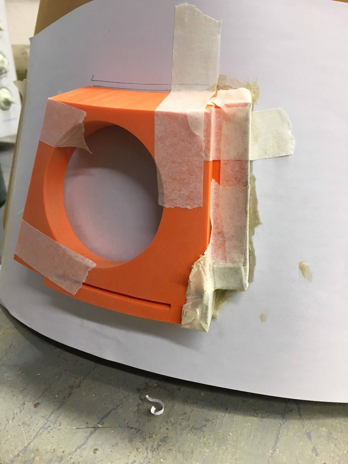
I taped a piece of paper onto the dome as to where the Radar Eye will go. This was to stop it messing up my nice clean surface lol. I then mixed up some glass fiber and applied it to one side of the eye's cardboard'd edge.

Lunchtime, I got on with cutting the radar eye's lens. I marked in position and then using a saw, cut to size.
 
After this I applied glass fiber resin to the other side edge of the radar eye, as the first side had set, as seen in the above pic.

~~~

Marking and grooving out the panels....
There are a few different 'styles' for the panels on an R4. The paint/colour design is another thing too. So I'm going with a standard'ish design.

I started with the 'lid' panel.
Drew on the groove details and then scored and scrapped out the groove detail.

I gave the groove a PVA wash to seal, and then once dried I lightly sanded them.
As the hardboard is only 3mm thick, the grooves are only about a 1mm deep. They are just for effect.

I drew up some templates in cardboard and cut them out. I then started to mark up the panels at the top of the dome.

I'll be taking the dome home again for the weekend, hopefully get some more work done on it then.

Looking forward to Sunday tho as a few members of the UK Builders are coming round to my house.....more info next week.

May 09, 2016

Bad Motivator - electronics/electrical work UPDATE 2

So Saturday I set up the electrics so I could easily work on them outside of R5's body.
excuse the hanging regulator, [mid left] this was just a wired up to test
I tested the new regulator and the bad motivator board worked.

Then I connected up the slip ring into the circuit, all good still.

Next, I connected up the door actuator ......and it didn't work properly!

Then realised I was using the old one.....so swapped it for the new one and, YES, it works. No fluttering! So I now know the old actuator is broke, cause tho??? We'll see how long this new one lasts.

~~~

Sunday I fitted R5's dome onto his body and re-tested everything.

Test one, motivator and smoke system work perfectly.
Test two, again, all works.
Test three......smoke yes, actuator not so great!?!?!

It activated and moved a little, but then stopped, not completing it's full travel.
And it also felt warm, need to look into this further.....

April 20, 2016

Bad Motivator - electronics/electrical work UPDATE

Fitted the XT60 fly lead and plug into R5's dome, then looked at the Motivator electrical system.

When testing the Bad Motivator system, connected to the main body power supply, the actuator's actions were 'pulsing/twitching' as if struggling to get enough power. So I disconnected the actuator and locked the Motivator in the 'blown' popped up position for events. I was baffled and a bit disappointed.....

This is the simple layout of the system:

After some thought, I deduced that the only thing different in the system when connected to R5's main electrical system was the Voltage regulator.

This is a 'switching' type, so no heat build up. This type is obviously fine with LED's, amps etc, but the 'switching' circuit [I believe] is the cause of the actuator's 'pulsing/twitching' problems.

So I've bought a 'normal' voltage regulator [like every one else does] to test out my theory.
Just waiting for it to arrive.....

July 17, 2015

'Bad Motivator' - upgrade to power lift 'Blown' status 2.0 [You-Tube]

So I was happy that the pop-up motivator system working, but not really with them ended both at the same time. As, well, in the film, after the smoke stops pouring out of R5,
his motivator is still in the UP position.


So I ordered another timer relay (that was delivered super quick) and wired this up to the motivator's actuator. With the intention of having different switch off times.


So the smoke and sound ends (once sound is wired up) and then after a while the motivator operation ends and drops back down. Sound sample was added to video for effect.

July 13, 2015

'Bad Motivator' - upgrade to power lift 'Blown' status 1.8 [You-Tube]

Installation Time!

Got home last night and started on fixing the electronics board into position. But soon realised that this position was not a good idea! Do to the material being screwed to was flexing and moving the outer skin. So back to the drawing board.

Whilst looking inside the dome, it came to me to just make a bracket and secure the board to the inside roof, like everything else lol

So in work this morning, I got to cut up an angle strip of Aluminium and drilled location and fixing holes into it. This can now be fitted and all wired up!

So on Saturday, I fitted the bracket to the inside roof of dome. Then attached bad motivator board to the bracket. Had to do some power re-wiring inside R5 to sort 12 volt power to board, then using multimeter, adjusted the voltage regulator to 6 volts. Topped up the e-Cig unit with some more fog juice and here's the first test video in action.

There was a bit of wind when I video'd hence the gaps in the fog showing.

I'll adjust the timer once the sound is sorted. Next is to wire up the actuator to pop up the motivator.

July 09, 2015

'Bad Motivator' - upgrade to power lift 'Blown' status 1.7

Last night I trimmed board down the board so it can fit in this position. Will have to reposition the timer relay.
Bad Motivator, R5D4Bad Motivator, R5D4


Dome wires previously set up for individual power of lights, motivator and smoke....not now required, so I could use these for other things (???) Only the 12 volt feed is needed to then be distributed to motivator and smoke via dome board.

'Bad Motivator' - upgrade to power lift 'Blown' status 1.6 [You-Tube]

Not had much time to work on this recently, but got back onto Monday.

I'd found a suitable piece of MDF that I could mount the components onto. I then did a bit of re-cutting of wires (see prev post pic) to shorten them to better fit the board and layout of them all.

Once layed out, I marked and drilled securing holes and fixed down with mini cable ties.
Not very pretty, but necessary.
R5D4, Bad Motivator

And here's the test video showing the timer relay in action. I connected an LED to the 12 volt output to show power, the voltage regulator has it's own LED power indicator already.


I just need to add some labels to identify what power and where wires go where lol.

Next is to test connect up to the Dome and the Bad Motivator & Smoke system to test for real!!

July 02, 2015

'Bad Motivator' - upgrade to power lift 'Blown' status 1.5

Components arrived at the weekend, sooner than I'd expected lol. But wasn't able to try them out till Tuesday.

As always the instructions for at least one components wiring diagram are......well, inaccurate......would be putting it mildly! lol. A black& white picture, no colour identities, component picture doesn't actually match the component! But it didn't take long to sort.

So this is the plan for connecting it all up.
R5D4, Motivator, Bad Motivator

And here's it all wired up for testing, using an LED as the motivator/smoke side of things.
The cigarette plug, connects to the 12v power adaptor.

And here it is again, this time with the voltage regulator fitted. Again, this is just a test fitting.
R5D4, Bad Motivator
The voltage regulator will be connected up to the smoke system (pump & E-Cig) as this runs at 6 volts. There will be another connection to link up to the 12 volt to the door actuator to activate the Motivator.

The remote triggers the circuit, which activates the timer relay, sending power to the motivator and smoke system. After the set time, the timer switches off and system deactivates. There is a bonus fail safe in that another button has to be pressed to reset the first button......well it's a bonus for now....lol