Back on it again these last few months, waiting for delivery of different components to get R5’s bad motivator setup all working from one switch off the RC transmitter.
Droid Builder
Extra Projects & Event Page's
- Home
- Event: Droids @Mshed Bristol 2026
- Event: Droids @Mshed Bristol 2025
- Event: Droids @Mshed Bristol 2024
- Trading Card Dispenser (version 2) - TCD [2020/2022]
- Trading Cards
- R5-D4's ....Bad Motivator development
- R5-D4 - silver neck details
- R4-D4 - Dome [wood build]
- R0-D4 Dome [wood build]
- 3D Printing - Star Wars stuff
- *** Star Wars Shoes ***
- Event's 2018
- Event's 2017
- Celebration Europe 2016
- Celebration Europe 2023
- Event's 2015
- Event 2014 - Chippenham Sci-Fi
- R5-D4 - events page - The beginning (2013)
- ** R5-D4 patch **
- R5-D4 Photos
- Costume for my Son - Han Solo -
- Costume for my Son - Boba Fett
- Droid Caller - Han Solo style
- Scanning Crew Container - Transmitter Storage Box
- Stormtrooper - me
- Rogue One - trading card storage box
- Rogue One
- GOUD-4 Messenger Droid - Solo ASWS
- Jabba’s gate prop for Celebration 2023
- Treadwell Droid - WED-15-77
July 07, 2025
R5’s Bad Motivator 2025
Back on it again these last few months, waiting for delivery of different components to get R5’s bad motivator setup all working from one switch off the RC transmitter.
September 27, 2023
R5-D4: Update May/June 2023
October 26, 2020
Sounds for Droid 2020 - 1.8 installation
Made up a new bracket for holding one speaker, out of some MDF wood. The prev one was perspex and was attached to the old sound board.
I may mount the second speakers in a rear position.
Continuing on with organising the wires, the slip ring underside wires are always annoyed me as they are stiffer due to less strands. This makes it awkward reaching inside as they get in the way. So I decided to cut them short and connect new, more flexible cable. This will also be yellow to match up with identification of the voltages, yellow being 12v positive.
Next up was to install the sound board. I changed my mind about which side to mount it on. Decided that it would be better over on the right hand side. I needed a spacer block, so cut a small piece of wood, marked the boards fixing hole position on it, then drilled clearance holes and screwed the spacer block to the frame.
Next up was to then mount the sound board to the spacer block.
I de-soldered the red power cable on the sound board and replaced it with a yellow one. I had some yellow heat shrink to cover the red wire for the Trading Card Dispenser electronics box.
Next up then is to connect the speaker, route the servo lead which operates the relay switch and test out the amp/speaker. Also need to look at where best to fit the volume control knob.
October 15, 2020
Sounds for droid 2020 - 1.7 Sound board build
Back in August 2020
After lots of design layout ideas, and 3D printing a special holder for the sound components. I decided to just go back to basics and use Perspex.....as I had found some spare. I still utilised the digital voltage meter holders & also the Dual Relay Switch holder, as these don't have there own fixing points.
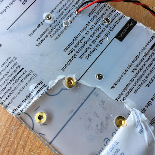
I dug out all the old nuts and bolts previously used and thought.....naaaa, I don't like the look of them. So I drilled a hole and test fitted a threaded Brass insert. It worked! So positioned the components, marked and drilled holes......all except the sound board (as this requires M2 size thread fittings) and then using my soldering iron tip, melted into place the Brass inserts.
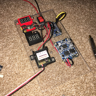
Next up was test fitting all the components on the perspex board.
Just waiting on the M2 thread fittings.....
I started routing and soldering the wiring next. I drilled holes to route the power wires behind the panel and to help identify the voltage, used yellow as positive for the Audio FX sound board as it uses a lower voltage than the amplifier.
The M2 inserts and bolts/screws arrived in a few days via eBay and where inserted into the rear of the board.
October 2020.....update
Got on with refitting the sound system. The extra perspex material has now been removed and a suitable location to mount it has been prioritised. A wood spacer block is needed to raise off the vertical frame support to allow the wires to fit behind. This new location is closer also to the 12v terminal distribution block.
I also fitted some of the new cable clamps I designed and 3D printed.
February 20, 2020
Relay switch holders - 3D printed
I designed this holder for the relay switch from 'Model Radio Workshop' (link)
It's just a simple holder to help keep it in place, once inside R5-D4.
I've also drawn up a dual holder, see other link below.
As per usual, I drew it up in AutoCAD Inventor, works program, and then printed it out on the Ultimaker S5.
Thingiverse Link
This dual version, is not just a simple, placing two of the above together, I had to modify the design slightly.
Thingiverse Link for dual holder
This was the third cable clip design I came up with. The cable easily folds around and slides under the clip, holding the relay unit in place.
February 17, 2020
Sounds for Droids - 2020 upgrade 1.1
Link to Sounds for Droids - 2019 upgrade 1.0
I didn’t want anything to complicated, so went for a design that will hold the relay in place with a cable retainer on the other end.
This was the first test print to prof the idea. The updated version will be a more snug fit....will know for sure once printed.
I left the screw terminals accessible for connecting up the leads.
January 23, 2020
Another mini project 1.8 - 'Trading Card Dispenser'
I was still waiting for an electronic component to arrive in order to wire everything up to test it. It arrived and it wasn't what I was hoping for, so I'll have to revert back to my original electronics setup, not a big deal as this doesn't effect the actual dispenser being assembled or operated.
I've designed this as a self contained unit with it's own remote controller & timer delay off circuit, but it would also be able to be controlled via any momentary switch, Arduino etc. I'm not an Arduino guy, but from what I know this is possible.
The motor runs on 6v and would only need to run for a few seconds.
The unit comes in 4 parts, base (in red), plate (in blue), lid (in green) & a wheel adapter which fits onto the motor. (colour's are for identification only, not actual)
There are then 4 components required to be bought in order to fit and glue together to fully assemble. I'll post up this list and an assembly instruction PDF when files are released.
More updates soon.......
November 27, 2019
Sounds for Droids - 2019 upgrade 1.0
The 12 channel remotes for controlling my R5’s sounds have, to my knowledge, never worked properly.
Think I’ve had three over the years plus the circuit board version that wasn’t what I thought it was, so was never used.
Holding the controller and the transmitter at the same time whilst trying to not draw attention to ones self at events (for the kids benefit of keeping the experience real) can be a bit of a handful.
I was all ready to bit the bullet and buy another one as my current sound setup has died. When Lee Towersey posted up a way to trigger sound directly from your transmitter switches using a relay!
I only have one three way switch available although I could possibly upgrade an ‘on/off’ switch to be able to operate more sounds as mentioned in Lee’s video.
So I’ve ordered one duel relay to test out. Checkout Lee's channel for the links also to the relay.
Next is to get a new sound board.