Droid Builder

Extra Projects & Event Page's
- Home
- Trading Card Dispenser (NEW version 3) - TCD [2020/2022]
- Trading Cards
- R5-D4's ....Bad Motivator development
- R5-D4 - silver neck details
- R4-D4 - Dome [wood build]
- R0-D4 Dome [wood build]
- 3D Printing
- *** Star Wars Shoes ***
- GOUD-4 Messenger Droid - Solo ASWS
- Event: Mshed Bristol 2025
- Event: Mshed Bristol 2024
- Event's 2018
- Event's 2017
- Event 2016 - "Celebration Europe"
- Event's 2015
- Event 2014 - Chippenham Sci-Fi
- R5-D4 - events page - The beginning (2013)
- ** R5-D4 patch **
- R5-D4 Photos
- Costume for my Son - Han Solo -
- Costume for my Son - Boba Fett
- Droid Caller - Han Solo style
- Scanning Crew Container - Transmitter Storage Box
- Stormtrooper - me
- Rogue One - trading card storage box
- Rogue One
- Jabba’s gate prop for Celebration 2023
- Treadwell Droid - WED-15-77
April 19, 2021
Sounds for Droid 2020 - 1.9 transmitter
October 26, 2020
Sounds for Droid 2020 - 1.8 installation
Made up a new bracket for holding one speaker, out of some MDF wood. The prev one was perspex and was attached to the old sound board.
I may mount the second speakers in a rear position.
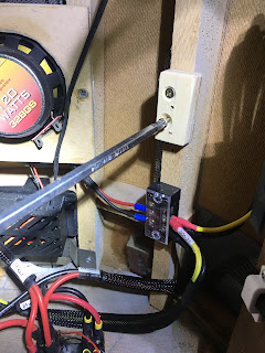
Continuing on with organising the wires, the slip ring underside wires are always annoyed me as they are stiffer due to less strands. This makes it awkward reaching inside as they get in the way. So I decided to cut them short and connect new, more flexible cable. This will also be yellow to match up with identification of the voltages, yellow being 12v positive.
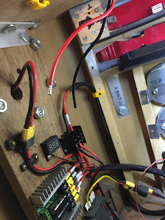
Next up was to install the sound board. I changed my mind about which side to mount it on. Decided that it would be better over on the right hand side. I needed a spacer block, so cut a small piece of wood, marked the boards fixing hole position on it, then drilled clearance holes and screwed the spacer block to the frame.
Next up was to then mount the sound board to the spacer block.
I de-soldered the red power cable on the sound board and replaced it with a yellow one. I had some yellow heat shrink to cover the red wire for the Trading Card Dispenser electronics box.
Next up then is to connect the speaker, route the servo lead which operates the relay switch and test out the amp/speaker. Also need to look at where best to fit the volume control knob.
August 10, 2020
Sounds for droid 2020 - 1.6 transmitter switch test
Forgot to post this.....
A few weeks ago I was asked to do a tutorial video for the Droid Builders UK Live 2020 event, check out the website here & the You Tube channel here. It didn't get aired due to time, but whilst I was working on all the electrical's, I swapped over the transmitter switch I had originally fitted, with a momentary version.
The original 'switch' was a dial which wasn't needed so after watching some YouTube videos on how too, I swapped it for a switch.
Here are my Blog links to prev. work done.
I wanted to have a momentary switch, rather than a normal 3 position one.
As I had already done the hard work in Parts 1 & 2, this was just a simple un-solder and re-solder the new switch.....except that what I didn't realise at the time was that the thread is an M6.....not an M5. So I'll have to make a new switch nut.
June 05, 2020
Sounds for droids 2020 - upgrade 1.5
In my last sounds post, I had thought about 3D printing up a sound board to mount the components onto, but thought this was just me having tooooo much free time, so decided to just stick with a simple perspex sheet.
May 14, 2020
Sounds for droids 2020 - upgrade 1.4
OTHER WORK
Since then I've been working on creating 3D printable enclosures to house all the pieces.
Sorting out the orientations of them so will post up once done.
April 28, 2020
Sounds for droids 2020 - upgrade 1.3
Rewind a week to the issues I had trying to upload the sounds to the board. I had just grabbed a usb cable I thought I had used before to connect the board to the laptop, but it wouldn’t connect???
After numerous attempts and system checks, I realised the cable was a power one not a power/signal one. Swapped cables and instantly problems solved lol.
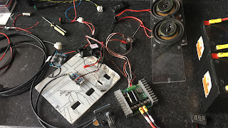
After testing the sounds using my phone, i needed to actually test with the sound board. So after some wire soldering/connections, the board, amp, speakers where connected. I had ordered a potentiometer as a volume control, but it still hasn’t come, so I dug out a broken large servo and used the pot out of it. Quick YouTube/internet search, and it was soldered up according.
This might look like a mess lol, but it was only for the purpose of taking the pic.
I opened up the ground loop unit to be able to connect up the speaker wires.
The amp uses 12 Volts, but the sound board runs 3-5 Volts, so has a mini voltage regulator [just seen in picture above it],
The sound output was great! And even more so, when I adjusted the 'volume' via the potentiometer, so much so that the wife told me to turn it down! :D
This new amp was originally going to be used as a separate sound unit for in R5's dome, but I think I might keep it for his main sound setup and get another [possibly] for the bad motivator dome setup.
Here's a size comparison between the two amps:
Tuesday 28th and the potentiometer arrived in the post...
March 30, 2020
Sound board enclosure - Prusa [was Thingiverse] Page
I've uploaded the stl file to my Prusa page, (was Thingiverse) but as I'm not able to print off and test, as usual, due to working from home in this COVID-19 situation, the file is deemed a Work In Progress. If you do download to print it and find any issues, please let me know so I can update the file to better fit.
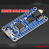
The above pictures show the designed enclosure, the sound board its designed to be used with and the final picture is my original sound board that broke, due to the plug bending and braking the socket off the board.
March 29, 2020
Sounds for droids 2020 - upgrade 1.2
My new Adafruit Sound Board. This is the 16MB version.
I got it from Pimoroni, here in the UK, total inc postage was £21.89.
Link to the product on the Adafruit website.
Link to Pimoroni website.
Next up was to solder in the contact pins
I only fitted pins i’ll be needing
and
then design up another 3D housing to print out at a later date lol.
This was version 1, I’ve since redesigned it to version 2.
Checkout my prev posts..
Sounds for droids 2020 - upgrade 1.1
And
Sounds for droids 2020 - upgrade 1.0


