Showing posts with label XT60 connectors. Show all posts

February 19, 2020

Electrical System Update 2020 - 1.2 cable tidy

Having ordered some more red power cable to reach from R5’s right leg to the Sabertooth speed controller. I spent a few nights soldering connectors, heat shrinking them and connecting everything back up, step by step.

The angled socket for the right side was also installed.
xt60

Next up I wanted to tidy them all up. I was never happy with the spaghetti mess before, so I ordered some protective cable guard. This stuff is great as it expands to allow the cable through, even with connections on. I then used heat shrink to close the open ends.
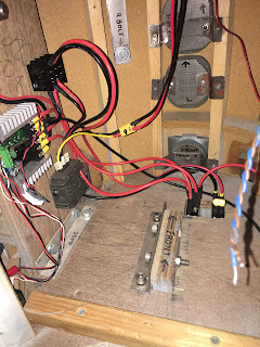
Here’s a ‘BEFORE’ picture:
new wiring
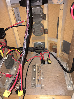
See below pictures for ‘AFTER’.

I’ve not heat shrunk all the terminals yet as i’ll do this once all the electrical testing has been done.
Really happy with how things are looking so far.
xt60, cable sheathed


sheathed cables
I still need to sort out 12v distribution from the regulator (grey finned box, bottom of picture, yellow & black cables coming out of it).

The dome motor controller location.
New power cables for the dome motor.
Power for the trade card dispenser too.

February 07, 2020

Electrical System Update 2020 -1.1 : 3D printing spacers

So in the prev post I printed these angled XT60 holders, that will be mounted to the inside of the framework for future removal of the legs (if needed).
xt60

I needed to make some spacers so that the cable would have a bit more bend clearance out of the bottom of the XT60 plugs.

Dimensions were taken off of the re-scaled version and after the second attempt at printing, these 3mm spacers print great. But they needed to be thicker, so had to print off a second set, which also required longer screws.
xt60

I then super glued the three parts together. I'll be fitting the brackets with the female XT60 connector, as the bracket opening is a snug fit and on testing the male plugs outside slightly deformed so making fitting of the female connector slightly harder to pull out to disconnect.

February 04, 2020

Electrical System Update 2020 -1.0

Did some more wiring at the weekend. The new switch position needed longer cables to reach the power distribution block.


Also fitted the switch panel into place.

I also test fitted the TCD (Trading Card Dispenser) behind the Utility arm. And temp fitted the control box to the inside of the frame. See next post for details and pictures.

Back to the wiring:
I am planning ahead this time with the idea of, if needed, being able to remove the legs in order for R5 to fit into my much smaller [than the wife's] car. This is something I had thought of when originally building R5, but due to set up time etc and being new, and the fact R5 could easily fit into the vehicle's we had, this was never needed.

So with this in mind, I wanted to fit plugs to the ends of the legs wires. Previously they were wired directly to the switch, preventing removal of them.

I had a look over on Thingiverse and found a few XT60 holder ideas. So why design one when someone has done so already. The one I used is this angled version, designed by Kamil Wijatkowski, link here.

The first print @100% was to big and the plug wouldn't be held tightly.
The second print I reduced to 90%, this was a better fit in one axis, but was now to narrow.
The third print, I mixed up the scales, 90% in the X & Z axis & 95% in the Y.
XT60 bracket

This produced an excellent tight fit!
XT60

Xt60

These are to be mounted to the inside of the frame for easy disconnection.

April 27, 2017

Control Panel upgrade 1.0 (2017)

This was more work I'd completed at the beginning of the month but hand't had time to post up:

With the new addition of the SyRen10 dome speed controller, I wanted the main control panel to be self contained. As I originally (due to time/space) had the 24v to 12v converter mounted on the sound board.

I wanted it tho to be independent, so with the panel out of R5's body, I got to work on re-working the layout to fit it all on.
R5D4
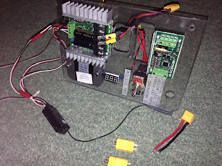
R5's Power control panel

Waiting on a few connector blocks and then connecting it all back up again.

So connectors came, heat shrink, cables & terminal block too. Any free time I spent on cutting, soldering (all connectors, non of this crimped stuff going on here!) then heat shrinking everything in sight lol.

Found a double sided sticky pad, for the transmitters receiver, to mount it on the panel.


The front view.

And part of the rear, view.

I say part, as the feet switch and cables are still inside R5's body, connected up. The switch goes in the hole next to the 'WARNING' label.

Next was to reinstall it back in place, wire up and test. The lead for the dome & the transmitter power were moved around. Power in was shown in the picture as channel 3, now in channel 6 socket - power. And the lead for the dome was moved to channel 4.

This is so that the left hand transmitter stick, auto centers after use.

April 18, 2016

R5's Slip Ring Upgrade 1.0

I wasn't happy with my original slip rings thin wires! For low level electrical signals they were fine for, but when my Bad Motivator door motor actuator operates.....it doesn't????

Bench testing connected directly to a 12V battery, it all works fine???

I thought it could possibly be the remote part of the circuit, but this is part of the same circuit that's connected to the 12V battery when bench testing, so I can assume this is not a problem.

These are the now 'old' wiring loom etc.
R5D4
 View up through dome base.

R5D4
Pin connection, wires to remote (upper right) & R5's eye sensors (left)

A fellow builder on the UK forum, was selling off unwanted parts, so I bagged me the slip ring he was selling. I then bought some XT60 connectors to connect up to the dome wiring.

Next, is out with the old connection and in with the new.