Showing posts with label R5's Legs. Show all posts

July 03, 2021

Corsa transport upgrades - 1.1

June 21st
After thinking about how best to support the legs. I decided that the solid shoulder hubs would be best, with a slot designed to hold in place.

I may still think about a central support, but the legs are solid hence not having them.

Next up was to support the ankle. The piece I had already made which would slot in the ankle and support on the bent steel ankle lock, needed to be modified to fit on the ankle support part.


~~~~~

July 3rd
With everything else going on, today was finishing up the leg platform.
So measured up, and got on with cutting out wood. All pieces were then glued and screwed together.
I added padding to areas needed to protect the paint etc. and these were covered in leftover red material.
And the finished platform…..

Tomorrow’s the big event day, for MOT’ing droids. Some have traveled far and are already in Bristol. I’ll be loading up R5 etc in the morning.

June 15, 2021

Corsa transport upgrades - 1.0

May of mentioned before, but my small Corsa, will probably be my main transport for events etc. for future events. The boot load area isn’t large enough to hold R5 in one piece, thankfully with recent upgrades the legs can easily be removed. Allowing a lot less weight to be lifted up and over the boot lip into the rear boot area.

So R5’s body and transport sledge location are sorted. Next up are the legs/feet. This required a new platform to sit over the rear seat area, when it’s laid down. Designed the platform to be level and to be able to be slid forward and use the supports in the boot area that support the raised false floor position.

Measured and cut up some wood and added some strengthening beams underneath.

Next:
  • securing points.
  • Strap/handles
  • Location mounts for legs.
I didn’t want the handles to be an obstruction so decided that as I have plenty of web strapping, I’d make two handles out of a piece of 10mm dia dowel, with the webbing fixed to them.

The second handle is fitted to the rear of the board, to be able to 'lift' the platform up over the side support end stops. The platform then easily slides up onto the rear of the lowered seat......as can be seen in the first picture above.

Still working out how best to mount the legs to the platform....

This picture shows the platform in its 'unloading' position, after being pulled forward, allowing easy access to the legs to be loaded/unloaded.

Am leaning towards the leg bolts as a fixing point and the ankles have a metal strengthening strip, so this could be the support point.

More updates soon......


..............Don't forget, the South West MOT day,
Sunday 4th July [UK only]

If your a UK Builder who needs a Droid MOT
[required for club approved events]
check out the Droid Builders UK portal link,
for the Northern & Southern events.

July 09, 2020

Funko Pop Astromech: 3D Body progress

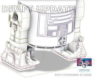
Yesterday I spent most of my free time drawing up the front panels, lower skirt with recesses.
The skirt recesses took ages as I had extruded it with angles, which caused me to struggle to then inverse 'emboss' the panel recesses. After a few attempts tho I got something that matched up with the original.

Next up then was the real fun part.....the panel details. I had to create a few different sketch layers in order to produce the recesses and then the protruding coin slots.

The Power coupling needed three sketch layers just for it alone. These tho I am hoping to be able to mirror to the rear of the model.
Funko Pop 3D

There's still a lot more to do, but it's really looking good to me so far.
Funko Pop 3D Body video
Created this short video of the panels being created.
#funkopop #astromech #thingiverse #3dprinting

April 26, 2013

Battlestations!!! ;)

What with R5 being on display this Saturday, am a little nervous, to say the least!!

Been trying to get as much done and finished before the big day, so yesterday, I sprayed up Leg No.2 white. I gave it a few coats, but as the can was running out, decided to concentrate on the outside/front. I won't clear coat it till the whole leg has been sprayed, but it still looks good.

I also sprayed silver the second Hub, that didn't turn out great the first time. And the rear strip for the Ankle Bracelet.

Then last night I started to assemble all the components I had for it. I first screwed into place the main Ankle Bracelet. It's screw although countersunk, is also covered when the Booster Cover is in place. Next on was the Booster Strut, which sits in the hole of the Bracelet and an angle bracket secures the top block to the leg. The Booster Cover then is just a push fit with the dowels, into the leg. The Ankle Cylinder [with wedge & holder pre-attached] are push fitted into place, along with the two Ankle Details. The Hub is also just pushed into place for now. And lastly the Horseshoe goes on.

Lastly, I started to dirty up the whole leg.


**UPDATE**
I've now fitted the Large Data Port, touched up the Octagon Ports edges with metallic blue, fitted the lower vent pocket mesh screen.

Outer Foot No.2 - UPDATE
Been working on the crescent detail, to finish off the top section of the shell. Also drilled out the knurled hose fitting holes and added the top strip detail. Only going to be able to primer it up for the show tomorrow.

April 19, 2013

It's the little things that are sent to try us.......


Yesterday I cut some lengths of thin hardboard to be fitted into the channel of the outer feet [internal]. All good. Angled edges, then primered & silver sprayed them up, nice. These will be screwed into place eventually, as they would need to be removed to get the feet off.

So, whilst waiting, I thought I'd test fit the inner feet & outer feet shells, plus the battery box 8).....only to find they they didn't fit!?!?!?! They were a snug fit before, but didn't think anything wrong as it ment no 'play' between the leg and channel when clamped together with the leg/foot bolt! But the extra paint on the foot internal channel walls, was enough to make the snug fit an interferance fit!!  :(

There wasn't anything I could do about the internal channel walls........so out came the junior hacksaw and started on slicing off the inside face of the leg ankle [bolt area]. Got so far, then had to swap over saw as then had to try to cut through the brass bush I'd fitted. This wasn't any good as the amount needed was the same width as the blade which just slid off. So out came the drill on it's slowest speed [so as not to make any noise, as it was midnight in my garage lol] and fitted with a countersunk bit, slowly drilled/grinded the bush down. I could then finish sawing the wood down.

This was just enough for the internal foot channel to fit over the leg, bolt section. Phew. Of course, this means I need to re-spray this area, but with not so many coats this time, as you won't see this area once assembled.

I then had to repeat this operation on Leg No.2. Not so bad as this one wasn't fitted to R5's body!!! hahaha.

Determind to reassure myself all was OK, I fitted his centre leg, and fitted his outer foot. And am please to report that it all fitting and looks........ fantastic :D
Put a bit smile back on my face I can tell you hahaha.

I'll post up pictures at weekend :)

April 18, 2013

Work update 2 - Outer Foot No.2 & Battery Harness Straps & Leg No.2


Leg No.2
Cut out ankle slot.
Finished sanding all over. But work still needed doing on the curve to get it smoother.
Then applied primer spray all over.
Then applied satin white, in stages, front/side faces then once dried, rear face.


Re-test fitted the 2nd outer foot internal assembly, and found that the leg end was to long for the channel. Basically, either the leg's hole was to high or the foot internal assembly hole was drilled to low or both lol. So I had to mark and cut off some material from the leg end and file smooth. This will need to be primed and sprayed again, not the end of the world as the slot & curved ankle area also need re-doing. Wasn't happy with how either looked so did some more work on them. Next re-sanding, primer, white.

Outer Foot shell No.2
What with R5 going to be on display, and whilst spraying up the leg. I decided to apply a few light coats of primer.
R2D2 R5D4 feet foot
Outer Shell No.2 WIP still
I also sprayed up the centre channel of the internal foot, visable when assembled.


Outer feet internals:
Applied primer to channel areas of the internal wheeled feet.
R2D2 wheels feet
Not the best shot, but this shows the internal side supports to stop the shell tipping
Then applied satin white. These are not perfect, but will do for now. When these are converted to the motorised version, they will be redone to a higher standard!
Started working on a 'strip' to cover the channel that will be sprayed 'aluminium'.


Battery Harness straps.
Hot glued on the blue details onto the two straps.
Then applied wood filler to the visable gaps.
Once dried, they were wiped clean of excess filler and will be touched up with blue.
Then I hot glued the straps into place on the battery box :)
R2D2 Feet
A before and after picture
R2D2 Feet
The Outer Foot Assembly No1....almost complete

April 15, 2013

Work update - Outer Foot No.2 & Battery Harness Straps & Leg No.2

Outer Foot No.2 work:
Internal Work:
Cut, screwed, drilled & fitted centre piece to clamp sides together. Made some spacers as the internal frame was a bit slack. Made up some side supports, to keep the shell level and square.

External Work:
Cut out the front and rear 'channels'.
Glued on the front plate where the knurled hose fittings go.
And also the rear plate.
Bonded on the last top piece of the shell.
Drilled and screwed side panel detail on, for hole ref at the moment. Still need to create the curve and top strip detail.
Started adding internal supports to stop the shell from 'wobbeling' on the frame. [two added so far].

Outer Foot No.1 work:
Silver sprayed up the front and rear strip details.
Started applying black paint and smudging it to look oily and dirty - W.I.P.


Battery Box Harness Straps:
Silver sprayed these two up.
Metalic Blue sprayed up all four details, these's will be glued on and additional filler added under 'blue' parts [and painted blue] once all dried.
R2D2 R5D4


Leg No.2
Applied wood filler over the back face of leg no.2 to cover the grain.
Started Sanding curved area, then applied some primer. This showed up where more filler was needed and which was then applied.


Finished of the second recess for the under shoulder stabiliers the other day, needs cleaning up round the edges with some wood filler.

Marked the ankle slot position, but this showed that the curve of the ankle was flatter on one side. This i wasn't happy with, so mixed up some car body resin & applied to area that needs building up more.

Transferred fixing points onto leg, ready to be drilled, these can just be seen in above picture.

April 09, 2013

Booster Cover No2 - complete


I've also been using the silver paint [pot] & brush to do the grooves on the booster cover. I wasn't to happy at first as it wasn't going on to thick, was used to the model paint I'd used before which did it in one coat. But after a few coats, it's not looking to bad.
R2D2 Astromech Booster Cover

next:
mark position on back face of booster cover for drilling and fitting of dowels.

February 17, 2013

R5-D4 - 3 Leg Mode :)

Had some time to do a little work on R5 the weekend.

I did some sanding of the foot base & started to mark the recess that i'll dremel out later. I cut the slots in the crescent & added a back piece. Also added wood filler to the sloped panel on it. (No photos yet)

I've been thinking about how to transport R5. So I thought I'd see what wood i had left in the garage. And was lucky enough to have 1 large sheet of 18mm plywood and another one half its size the same thickness. The reason I mention this is because it gave me the oppertunity to fully (legs) assemble R5!!

So on went both legs, then flipped him over to bolt on his centre leg.

Then I bolted on the only temp foot I have at the moment. What could I use to support his other leg?? The paint pot I had just brought out to be put away :D
 
R5D4 Astromech Droid
I didn't fit the foot shell, which I had, but this was just to see if everything worked
 Was a bit nervous, but everything worked and he looked good! :)

I also ordered a lazy suzan (cheep & small in comparison to what you guys use) but it looks ok and didnt break the bank. :) time will tell if its any good.

January 26, 2012

Leg Booster Cover Unit 1.6


Made a little progress this week. Made a cardboard template up for fixing dowels. Crafted the two remaining lower front grooves. Applied wood filler & did MORE sanding to curved/slot detail of booster cover. Primered with several light layers. Cut up four dowels roughly 20mm long (dia9mm).
The extra work needed to tidy up the two top slots has meant they have got smaller. I hope to be able to enlarge them back out to the correct size.

Next: using the template, I marked & then drilled four holes & push fitted the dowels into rear face of booster cover.


Extra work done:
I also trimmed excess resign from base 'insert' I fitted the other week. Sanded, then applied wood filler to gaps.

December 15, 2011

Ankle Bracelet 1.2 - primer & silver paint

Sanded the ankle bracelet and sprayed primer.


Later, added some wood filler to a saw cut to deep.
Sanded flush and then re-primer sprayed, then once dried, sprayed silver.


December 09, 2011

Ankle Cylinder Holder 1.2

Applied some wood filler to spots on the holder and also over the side faces to get rid of the wood grain effect.


Once dried, I'll sand smooth. I'll also use a length of tube with sandpaper on it to achieve the curved cylinder contact surface areas.

December 08, 2011

Ankle Cylinder Holder 1.1


Marked up and cut out of 18mm hardboard, the first, of two, Ankle Cylinder Holders. These pieces sit underneath the cylinders on the Main Legs.


I don't intend to curve the full length of this for the cylinder to sit in, just the ends. The middle part has been cut away completely.


Carved out section
Rear section
I used my dremel with a sanding wheel to create the cylinder curve.

November 21, 2011

Shoulder Horseshoes 1.1


Bought 3mm thick hardboard for making the shoulder horseshoe build ups. Got the wood from B&Q for £3+.


I had to double check I had the right piece as the price had gone up over a £1 since April, when I first saw it!


I cut out the three different horseshoe template sizes I had printed out onto paper, that i'll transfere onto the hardboard. I'll then cut them as square blank, screw them together and cut out each set with the jigsaw.