Showing posts with label R5's Outer Feet. Show all posts

May 29, 2023

R5-D4: Update April/May 2023

I’ve been giving R5 as he hadn’t been actually moved since Birmingham at the NEC.


New Dome motor wheel:
3D printed him a new wheel, as on the previous one the retainer nut wasn’t being held well and the PLA had been stretched. So I slightly modified some of the sizes and then printed it in ABS. Fitted the nut and 'o’ring and then fitted it onto the motor shaft.

Test was on Saturday at…..
 ...April

Next up was to connect up the new receiver. This didn’t take me to long, compared to the nightmare I had trying to sort it out when at Celebration 🙄.

I didn’t need to connect power (previous TX require power), this one utilities the power from being connected by the servo leads. Jacking up the wheels meant I was able to setup the drive and steering channels, plus the extra switch ones, for the utility arm, sounds and (once I have the long enough servo lead) I’ll be able to trigger the trading card dispenser.

Trading card dispenser:
A while back, I made a new trigger control box that utilised a servo controlled relay, instead of the previous remote control. Once the servo lead arrived, I crimped on new plugs to connect up the TCD control box.

View Blog post here.

But on testing it….. I realised that it needed to have a momentary activation rather than an actual ‘switch’. So I’ve been on Radio Model Workshops website and will be ordering a single RC switch relay, which has the option of it being a momentary one. So this control box will get another upgrade when it arrives.

In the meantime, I swapped the control box back over to the remote control version and 3D printed a new box for the remote, so that it could be attached to the new rear panel I’d printed off for the new Flysky transmitter.

I drew up a button bracket, that fits into one of the rear screw hole sockets, this will be upgraded again to look better and also hold the LED in place.

May 9th

Outer foot ankle lock:
The outer foot shell needed some repair to it, so with the legs off the body, I stripped the outer foot down. The ankle locks unbolted and the ankle bolt nut (previously held in place with super glue), fell out lol. I knew I needed a better way to hold them in place. I had thought about a lock washer, but then a lightbulb 💡 moment came. I measured up and drew up a nut holder to 3D print. It would be held in place by a bolt.
Nut holder loose.

Nut holder moved into position. I applied some thread lock to help keep it in position, but only nipped it tight to allow the ankle bolt to locate through into the thread.

I’ve added the file to my Prusa page.

The wooden foot shell got cleaned up inside to allow the new glass fibre to bond properly. Good as new again.


June 19, 2022

Reinventing the wheel……

😄😄😄 lol, yes…..aaaaaand no.

Back in April (last month)….
R5’s ride height has always been an annoyance for me over the years. Most noticeably at events on nice flat surfaces where I can clearly see the wheels. [for film appearance's 😎, this isn't so much of an issue]

Also the feet internals weigh quite a bit and they don’t support the floating foot shells very well.

So, I decided I needed to redo them to be lighter and lower.

Using my original internal feet frames, I drew the new versions up in AutoCAD inventor and then 3D printed out these test pieces.
This build structure is not new, but as buying the components might not fit my 'UNIQUE' foot shells, designing my own to fit made sense.
Above is first draft printed. The cut outs were just to save filament.

Test fit inside the foot shell.

And showing the reduced protrusion from the bottom of the shell.

I’ve ordered some aluminium plate, for the frames off eBay.

The first sheet of metal arrived.

Nice……👍🏽

Due to a family event, the funeral of my Grandmother who reaches 105years, the project was paused.

May 2022
Tuesday 3rd: was cutting aluminium plate day. I got out a hacksaw and started cutting out the main side plates.
I was also figuring out bolts, spacers and nuts.

Additional plates are on order, the two hashed areas on the 3D prints [above picture] are not needed so will be removed.

Found some suitable Stainless Steel tube, which will be great as the spacers.
I’ll be using M6 bolts and Nylock locking nuts, which I bought from local DIY store.

The steel tubing needed to be squared off at the ends, so used the lathe.
The bolts have washers both ends and locking nuts.
I drew up a shell support to help keep it from tipping over, as the shell 'floats' on the inner frame. This I 3D printed off to save weight. It's held in place by the longer bolts, washers, nuts.

Next up was creating retaining clips for the aluminium channel strip. First idea was hollow, but thought, it doesn’t have to be. So cut it in half and turned it into a clip, that snaps over the spacer tubing.

With the new frame layout, it will also be easier for me to access the ankle bolts, nut. On the original steel frame, I had the nut welded in place. Now, I’ve got nylock flanged nuts.

Next was to drill location holes for the front caster mounting, angle plates. And I positioned the caster to be more inline with the rear wheel.


And here’s the completed assembly, with motor and caster fitted. This whole assembly is so much lighter than the old one.

I have already made a start on cutting out the second set of plates. So this will come in a following post.

June 2022
Back in work after a short break away and back on with cutting out plates for foot no2.

….a rushed week of getting everything sorted before attending Saturday 18th’s event at Stars of Time, in Swindon’s steam museum. But got everything installed Friday night lol.

Event report to follow…..

June 11, 2022

Busy week: R5 motor bracket/3D designing and more….

 A busy week of building, buying, designing etc….

1:
R5’s second new foot motor bracket frame, needed completing: just needs some finishing tweaks, and 3D printed brackets for the channel plate.

2:
Been discussing in group chat about next year’s Star Wars Celebration , attending droid numbers etc.

3:
Been designing up ‘control panels’ for a side project idea. See coming post.

4:
Whilst researching I came across a video about the origins of R2’s PSI lenses. So a search on eBay and I managed to get a bargain for £6.00 GBP. Its a vintage Weston Masters two, photographers light meter.


The lens is bubbled on one side, but i was surprised to see that the honeycomb part was multiple layers of punched/stamped pieces, that were then rivited together.

April 13, 2021

Funko R5 - Outer Foot file [upload]

 So for over a year, I thought the file for my outer foot had been uploaded to Thingiverse, and as nobody had asked about it, I would naturally assume that all is well with the world lol.

Till this morning, when I received an email from Scott, thanks Scott, asking about said file......

....due to the issues, Thinkgiverse uploads, the file hadn't uploaded.

So for all you Funko fans, the file HAS been uploaded [here] AND added to the original R5-D4 Funko files [here].


August 06, 2020

Funko Pop Astromech 3D - build update

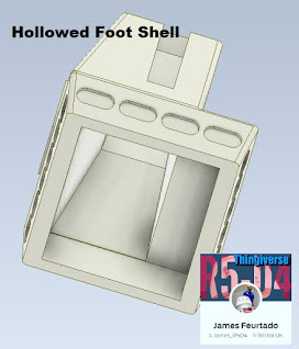
Hollowed outter foot shell
Been working on a fully assembled printable version as well as one without the 'bobble head' effect, similar to some of the other Funko Astromech's produced.

I've also been reducing the amount of fill, see image above, by making some of the components, hollow. To print a full R5 would take around 16 hours, assembled, though printing the parts as individual's takes about 18 hours.....

......more progress updates soon.

July 09, 2020

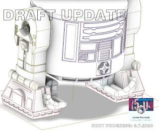
Funko Pop Astromech: 3D Body progress

Yesterday I spent most of my free time drawing up the front panels, lower skirt with recesses.
The skirt recesses took ages as I had extruded it with angles, which caused me to struggle to then inverse 'emboss' the panel recesses. After a few attempts tho I got something that matched up with the original.

Next up then was the real fun part.....the panel details. I had to create a few different sketch layers in order to produce the recesses and then the protruding coin slots.

The Power coupling needed three sketch layers just for it alone. These tho I am hoping to be able to mirror to the rear of the model.
Funko Pop 3D

There's still a lot more to do, but it's really looking good to me so far.
Funko Pop 3D Body video
Created this short video of the panels being created.
#funkopop #astromech #thingiverse #3dprinting

September 22, 2015

R5D4's Outer foot - shell repairs

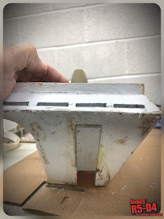
The outer feet foot shells were showing signs of wear-n-tear and needed some TLC.

They were not designed to be resting on the thin edges of the newer internal metal frames. This has caused the joins to split apart in places due to the also 'thin' ankle wedges.

So, as I still had fibre resin, from making R5's dome, I started cutting strips up ready to bond onto the joins. Then once clearance areas were clearly marked, started mixing up and applying the resin to the fiber strips.
R5D4 outer feet shell

R5D4 outer foot shell

These feel much stronger now and the new ankle brackets mean there's no forces being applied directly onto the shells.

Think I still need some more support but for now they'll do.

September 04, 2015

R5's outer feet, Ankle Lock, upgrade - 1.1

Yesterday morning in work I cut to size, filed an angle and drilled a hole in the first ankle locking strip.

This is how the outer feet looked before, here with front caster.
R5D4
I wanted to keep the area of support as large as possible, hence keeping the motor wheel at the back. This had recently been talked about with other club members. As R5's dome is larger height wise, than an R2 unit, his centre of gravity come's into play.

I then positioned it and marked where the hole will go in the channel of the internal metal foot. Then it was a case of cleaning up edges and fitting all back onto R5. The moment of truth....part 1.....

R5-D4
 Look, no front caster.....magic..... lol

R5D4, Star Wars
 Rear shot.....

R5D4, Star Wars
The nice large M10 cap head bolt holding it all together.....

The locking strip has some spring in it which I'm hoping will make things not so rigid.
I need to sort out painting up the strip to better 'blend in' with the leg, but that's once it's all done and tested.

September 02, 2015

R5's outer feet, Ankle Lock, upgrade [& new centre foot wheel]...... 1.0

R5's outer feet were built, as most peoples are, to spec, well mine were as close as lol.

With a single motor wheel and caster at front to ballance, the wheel/foot assembly, then requires ankle locks to help stop the front caster from tipping the foot (due to its diameter being smaller and often 'digging in' where a larger diameter wheel is be able roll across a hole/gap). With how my outer feet and internal frame work is the locks are not the greatest, well, they're ok flat smooth surfaces, but anything slightly uneven and the 'panic stations mode' is flipped!

So the plan is to change his internal feet to better support driving him, real world situations, hopefully, reducing the worry of him tripping over.

Recent event's have confirmed that the casters are definitely the week point on any surface other than flat & smooth! So am drawing up some ideas on how best to fully lock the feet, whilst trying to keep things atheistically pleasing to the eye.

With R5 putting his [outer] feet up, I needed to replace his centre foot wheel. This may also need a future upgrade, but for now, just a new wheel was needed. The size I wanted I could only find at the original place I had got the first one from, B&Q!
R5D4, Star Wars

The original one has worn down and although a harder compound wheel would be more suitable, the size to fit in is the limiting factor. I am looking into similar sized scooter wheels as they're material is harder, so won't wear out as much! [W.I.P.]

R5D4
Spent bout 45 mins, looking for suitable size/thickness wood, figuring out how to best fit it..... When I found some metal strips that would be perfect. So bent one to the angle required and then marked for cutting.

I found a pair of M10 cap head bolts that should do the job of holding the angles in place. I just need some nylock nuts.


July 27, 2015

R5-D4's transport platform 1.5 - UPGRADE

Saturday, I got to finishing off some things that needed doing to the platform to make it actually fully useable lol. As it was, there was no where to mount his centre leg and also he wasn't securely stable if platform was moved.

Original location bolt holes for the stand were no good once the car ankle stabiliser stands were used on the platform. So I made and fitted two location pins for the stand. These are just to help stop things moving around.

Platform now fitted with location pins for stand

The batteries can be stored under the stand.
R5D4R5D4
The foot/ankle stands also fit on the platform. These may also get location pins, but as the whole lot gets strapped down, they may not be needed. 

R5D4
In the previous pictures, you can see the new 'slot' to the rear of the platform, between his legs. This is where his centre leg 'slots' into place.
R5D4
R5 fully installed on his transport platform. Just need to add some location points for the battery boxes to secure them and also some storage for transit bolts and tools.

I'm considering installing some sort of push bar to be fitted to the base, rather than have hand's on his shoulders.....

His head will be fitted onto his body, it is now for storage purposes.

November 26, 2014

Outer feet - weight reduction 1.1

R5-D4 outer feetR5-D4 outer feet

Re-assembled all the components into the inner foot frame. I used loctite on the bolts that hold the motor in place. Then after locating the drive belt, re-fitted the rear wheel, along with its upgraded spacers and washers. Looks and feels so much better :-).
Lastly I fitted a black front caster. It needs to be lubricated as isn't very free moving.


Before assembling I did weigh the frame and it is slightly lighter..... lol :D

R5's outer feet casters were white and were only used as I had swapped them over from the the feet internals that allowed R5 to be pushed around on. This one has now been changed to a black one, need to buy another one, so I hope, they will not be as visible.

November 24, 2014

Drive wheel brass bush's upgrade work

On stripping down the feet internals, I noticed that there was some brass 'dust' residue on the bush's. On closer inspection I realised that I had not machine turned the diameters on the ends that make contact with the wheel bearing face and they were rubbing on the outer diameter face.
R5-D4

So in work, I machined both pairs down in size.

R5-D4

I needed to make up to new washers, as was easier than trying to modify them.
Old washer, far right of picture, for size comparison.

November 23, 2014

Outer Foot No.2 - Bolt locking issues

This afternoon I removed the internal motor frame from the shell, with the intention of stripping it apart to carrying out the weight reduction process as for frame no.1, only to find it wouldn't come apart? On looking inside I found one of the motor bolts had come loose! I managed to get the internal frame out and found that the other two bolts were loose.these do have barbed locking washers, but I think I may have to apply some loctite thread lock!

November 21, 2014

Outer feet - weight reduction 1.0

The internal metal frames for R5's outer feet, are heavy! They weigh 3.5 Kg each without the shell or battery box. And once the motor and wheel is removed, 1.5 Kg.

So I started looking at where material could be removed to reduce weight, though I don't think this will actually make much if any difference??

Finished the first 'wave' of cutting and weighed it....... unable to give a reading, lol.
So back on the milling machine to remove more metal :)

October 30, 2014

R5-D4's transport platform 1.3 - UPGRADE

R5-D4 when built fitted into the boot/load area of MY Zafira just fine. But the wife's newer one, the hatch is smaller in height.
Meaning the feet have to come off. This was something I would of preferred not to have to do, because then I'd have to figure out a way to support R5 in no leg mode!

This is not complete, but is on it's way to being. The centre leg would have to come off due to the limited height.


So I built this mini platform, which will also double as an assembly stand once attached to the mobile platform. The mini platform fits onto the mobile platform, giving the right amount of clearance and stability to re-assemble his feet, then he can be reversed, giving access to the stand, which once moved, allow's me to re-fit his central leg/foot assembly. Phew.

The left pic shows how the stand will be once R5's in place, the right picture shows the stand aligned with the edge of the platform, this allows the outer feet to be re-attached with plenty of ground/platform clearance.

I thought about if I needed to transport from A-B without having the space (or dry weather) and needed to move everything quickly. So thought and made up these to channel runners to bolt the outer feet too. The ankle bolts hold them in place whilst in transport, also means I can't misplace them lol.

I still need secure the centre leg and re-do the strap U-bolts (at the front of platform). Of course the proof will be when it comes to using it if this works or not lol. But, I know that with his feet off, I'm able to lift him up and into the boot again.

July 21, 2014

R5's got new shoes..... (Feet motor's are fitted)

Reassembled internals on foot no1. Motor, belt, wheel, then into foot shell and locked in with the aluminium channel strip. I then fitted back onto R5's ankle.....


Ooops, I forgot that the securing ankle bolt needed to be cut short. It was that long to go through two pieces of 18mm thick wood!

Next problem I found. The gap between the side channels is slightly to wide and there (rightly so) is no flex of give in the metal channel plates. So the ankle bolt doesn't force the side channels to clamp onto the legs ankle. Again, the wood in the old internals did flex to clamp.

Lifting the body showed that the new foot is well balanced. But because the foot is not clamped I need a lock....an ankle lock. So out came the paper and pencil and traced up a wedge. Now because my foot shells are wood, the only place I can apply the wedge, in the hope it will work and not damage the shell, is on the inside face of the leg, so that the force is transferred to the metal motor frame directly below it.


And here it is, screwed in place. Let's hope this works......?

YES, it works! Well in lifting the foot and trying to tip it forward it stops it doing it.
Just have to see how well once fully operational.
And here are both new feet fitted, with there locking wedges.