Showing posts with label carbon fibre. Show all posts

October 17, 2024

Treadwell WED-15-77: mast box build (not yet made)


March/April 2024
With the tracks completed
(at the time of writing this), and after making the head box, I needed a storage/transport box for the ‘mast’ section.

This was going to be built using the same design as the head box. I 3D printed the corner pieces again and then modified a copied version into a middle section.

I bought some more carbon fibre wrap and plastic edging.

October 2024: this still hasn't been built yet.

January 13, 2024

Treadwell WED-15 : Head Box build - part 1

December 2023:

Head box - transportation/storage
This was something I needed, so I measured & sketched up a suitable size box, allowing for foam padding. The box lid is going to be the top third of it, so that the foam insert, helps hold the head in place.


  • I already had 3mm thick wood hardboard.
  • Bought a length of some black 90° angle plastic.
  • Bought some carbon fibre wrap and some catches.
Cut some of the wood to size, but didn’t have time to cut the fourth panel. (Forward to January 2024). All the panels are going to be secured with pop rivets……hopefully. They seem to be doing okay so far.


January 2024:

Cut the fourth panel out. Then cut all the panels to create the upper lid pieces. The smaller pieces in the picture below. [These I didn't actually use].
Cut to length the 90° angle plastic, and miter trimmed the edges.

Cleaned the edges and then took them inside the house to measure up the available wrap.
I made sure there was enough to overlap the edges and stick to the inside faces. I also made sure that the wrap weave was all going in the same direction.


Next was to mark and drill holes for the pop rivets. Not sure yet if i need to add a second internal 90° length of plastic.

I marked and drilled each hole one at a time and used rivets to help locate correct position for the next hole.

Corner pieces: Base
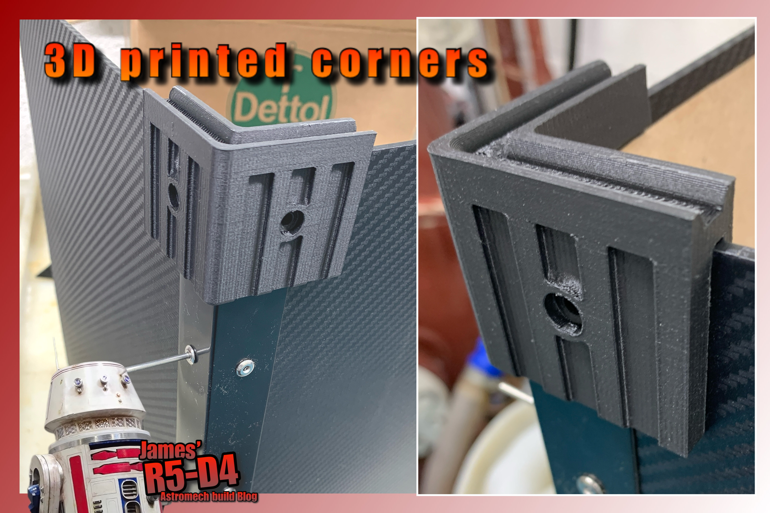
Looked at buying some, but wasn’t happy paying for something that wasn’t going to work with my design……so I drew one up in CAD. Added recessed so that the plastic angle would fit underneath. Securing holes for fixing to the wood panels. Added some ridges to the sides.


First 3D print worked. So set the printer to run overnight. These didn’t print, need to check and clean the printer??
But got them printed in the day. Am really happy with how they turned out. They really add rigidity to the box sides.

Next up was to add plastic side edges, drilled and temp held in place with rivets.

Corner pieces: lid 1 & 2
I then got on with designing and printing the lid corners. These have a lip to fit over the sides and then a recessed lip which will hopefully align with the upper lids corner pieces.

The upper wood pieces previously cut, now aren’t needed as the box has enough height to accommodate the ‘head’ + foam insert protection. [measure twice, cut once lol]

The upper lid corner(s) was drawn up for 3D printing. These have one length edges as well.

Next up was the edges around the lip of the box. These incorporated flats for the clasps. First lid corner/length piece printed, sketch image above, and picture below.

Even after cleaning the nozzle, the Ultimaker is still acting up, so can’t do any overnight printing. Came in next morning to find print had paused again.... noticed an exclamation warning...... on clicking on it, it showed the print HAD paused at layer 69, because I had told it too!!! 😂😂😂😂 I remember now seeing if the pause function worked, but as recent prints weren't high enough, I had forgotten this tick box. Hopefully everything will be back to normal.

First box length piece printed, after pause restart lol. I printed it longer than needed so it could be trimmed down to size. It's not a tight fit between the corners.

I drilled a hole for the pop rivet. But will add two more either end [see image below].
Next up was to position the clasp and screw it in place.
Each day, another piece was printed. To help strengthen the lid joins, I've printed some corner that fits on the inside edges.


The box isn’t going to have a lid handle, but two side ones. These I've bought off eBay.

I also printed off some yellow infills to identify the front orientation fo the lid to the box.

I’ve ordered foam for inside, so fitting of this and the handles will be in part 2.

January 29, 2023

Treadwell WED-15 droid build : Part 10 - painting

Treadwell droid
Progress made includes:
  • Second Arm - 'Clip' type
  • Replacement servo arrived [though probably not needed now]
  • First Arm - Claw arm work
  • Third Arm - Two prongs
  • Fourth Arm - Probe
  • Cables & tubes
  • Painting
  • extras.....
Second Arm: 'Clip' type:
This I call the clip arm as it's end resembles a clip you would fit a pole/broom too to locate/store it. Using previous images, I guessed a suitable size and printed it in a flat orientation. This allows for some flexibility without it (hopefully) breaking.

I used the large 8mm dia carbon fibre tube as the second stage of the arm. The clip fits onto this.
Treadwell droid, utility arm

Treadwell droid, utility arm

Next up was drawing up a new bracket. I'll use this design for the other arm brackets.
Once I'd sanded these pieces and had shaped the pivot location pin, I then drilled and screwed the bracket in place. 

Replacement servo:
The one purchased off eBay, had a piece missing out of the bag. Sourcing this item would not of been cost effective even with the partial refund given. So the seller posted me a whole new servo unit, which included the missing piece. Great!
But I don't think I'll be actually using it now..... so I'll save it for another project..... or will I....... I've just had an idea! So some more development work on this soon.

First Arm: Claw arm:
Finally the main 'Claw' arm. I needed something that could be flexible but still be able to transfer movement. I’d looked at bowden tube designs, bicycle break cables etc. Settled on an electric guitar string. This should work well, next was to locate and rig up the mini servo to it, through the new tubing, and connect to the Claw.

Third Arm: Two prong arm:
After I'd drawn these items up, they were printed off, overnight, plus an extra bracket for the last arm. The holes in them were Dia 6.4mm, this allowed for material expansion of the filament during printing, and allowed a snug fit of the carbon tube into the parts. A Drill bit was the only thing I had to use to help clear out the support material inside the holes.
A lot of sanding and smoothing to remove the print lines on the two tube arm sections; as well as the bracket.
Treadwell droid
Cut the carbon fibre tube down in length to better fit. These will be glued together eventually.

Fourth Arm: Probe arm:
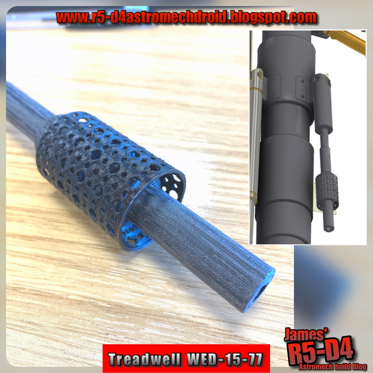
This one I drew up in 3D, basing the design on the one Paul6700 had originally made. It can be seen in my above picture (on the right). I liked the mesh screen too, so had a go at printing one off. The first version, showed up its weak points, the holes were too close together, so the second attempt had larger spacings and worked great.
Treadwell droid

Cables:
I wanted to replicate Paul’s and the original WED cables, using vintage wires. I dug into my box of old iPhone charging cables lol, as I remembered that these (older versions) had metal wire sleeves under the rubber insulation sleeve.
Tubes:
The plastic tubing I had was the right size, but was still a bit too stiff, I wanted something more flexible that wouldn’t hinder the movement of the claw arms motion. I searched for silicone hose and found translucent tubing. The right size was available and it’s really soft and flexible (eBay).

Painting has begun.
Sunday 22, bit chilly but decided to make a start on spraying up parts. The eye units, the neck and base plate parts, were primed first.
Treadwell droid

Treadwell droid

Treadwell droid

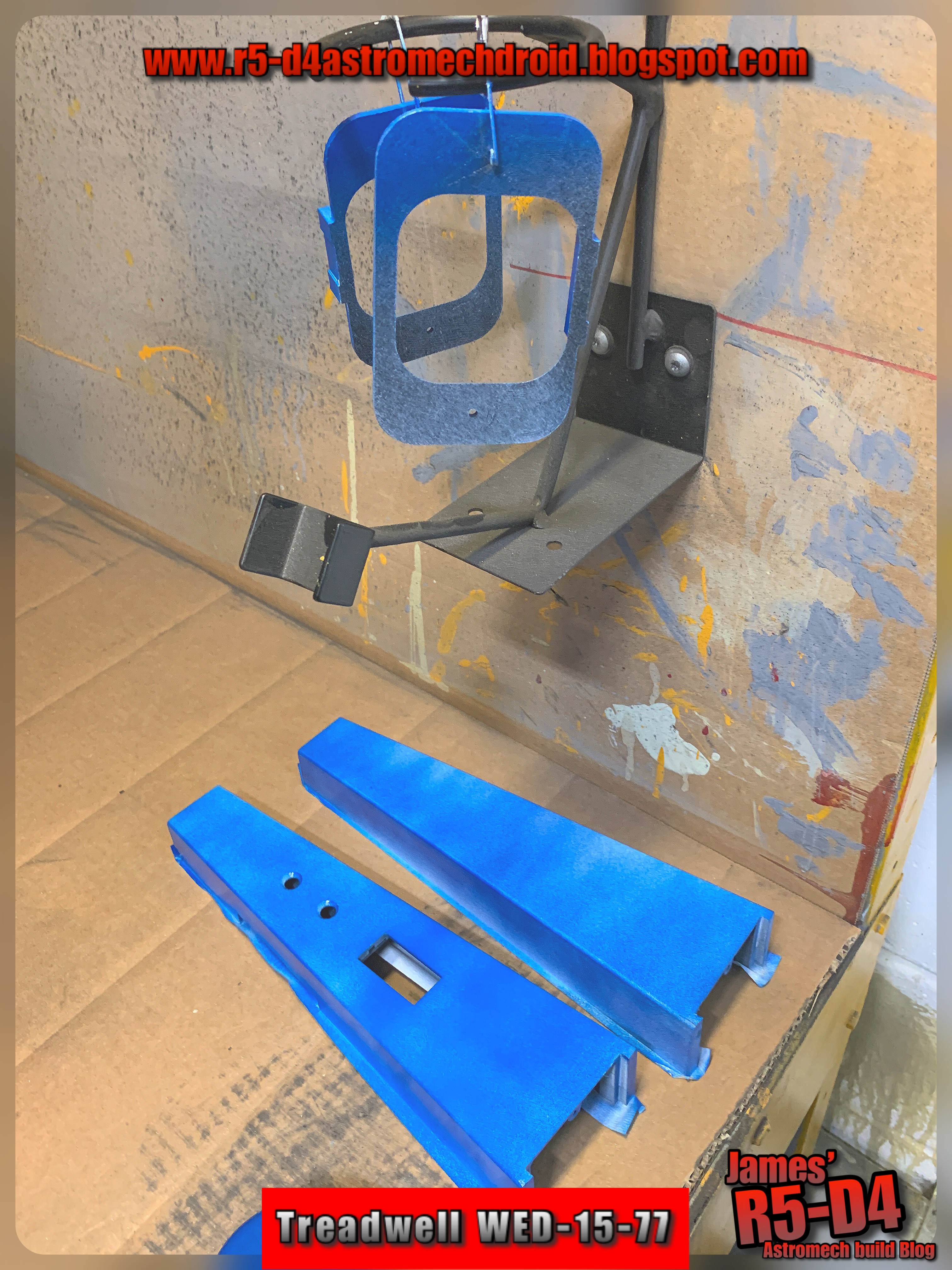
Monday, I found (I hope) a suitable blue spray paint for the eye units, and later, for the base. Picked up two cans.

Tuesday, I took the pieces I wanted to spray up, into work. They have a spray booth and it's inside in the warmth lol. I used the metallic silver (what was left of the tin) to spray up the base plate and the eye brackets. I had added some super glue the night before to areas that the primer didn't fill in. This actually adds to the effect, along with the print lines looking like machine lines. Result!

Treadwell droid

Treadwell droid

I next sprayed up the eye units with the blue spray paint, I think they came out ok. I did make the mistake of spraying the eye that's still in two pieces separately, so these will require a respray together lol.
Treadwell droid

Treadwell droid

Treadwell droid

Treadwell droid

Finished look.
Treadwell droid

Wednesday, I primer sprayed the arms.
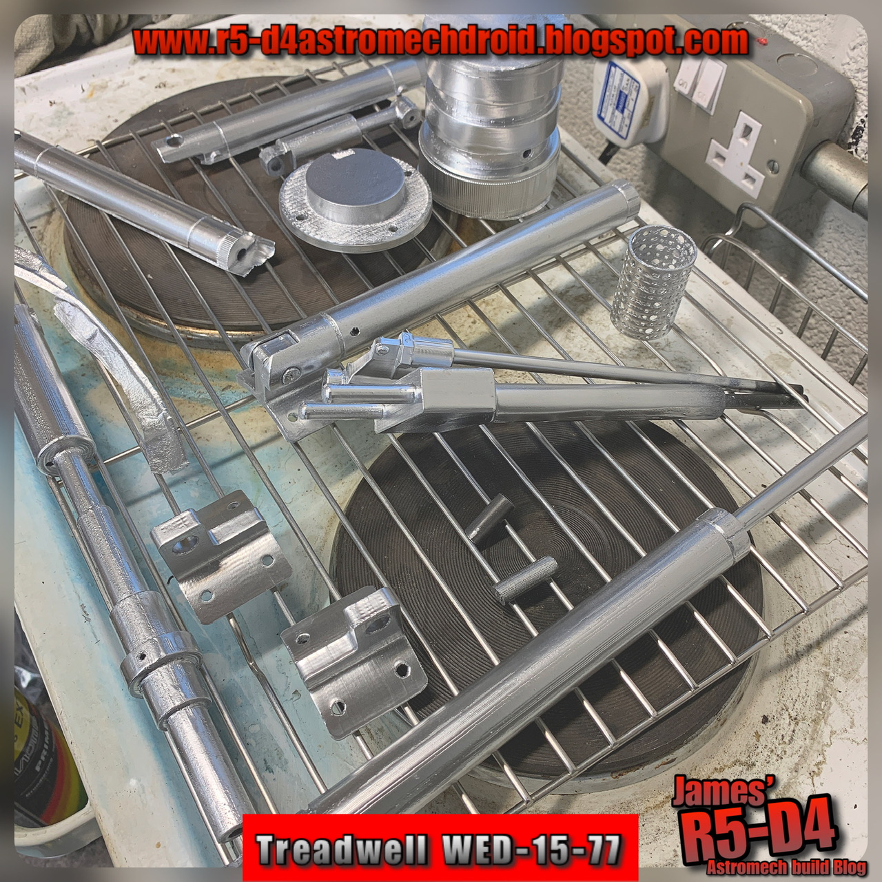
Thursday, the arms etc got the silver spray treatment.
Treadwell droid

Extras....
Lastly, I drew up some extra pieces and test printed them off. These include covers for the bottom of the eyes, where the legs poke through.
Treadwell droid

I have also drawn up and printed off a new upper neck servo mount as a test piece. This would replace the need for the motor to turn the head assembly left and right. I've incorporated the bearings in it again, to help take the weight off the servo. This is still a WIP, as I need to see if the servo is strong enough to move the weight of the head, more soon.

February 26, 2021

R4-D4 dome - Life-form scanner final design - part 15

 Sooooo...... :D yes, I think this is THE final incarnation of this 'little' project lol.

I suppose this version was inevitable as this project has progressed, but the intention was to just have an independent set-up. So why have multipile components, with possible alignment issues etc. This design now incorporates the Pie hole panel and the life form scanner as a one piece unit.

life form scanner, r4d4, pie hole panel,

The colours show the (modified &) combined components.
  • ORANGE = modified Pie Hole Panel unit.
  • BLUE = upper servo lift bracket
  • RED = upper LFS bracket
  • YELLOW = LFS bracket cover
  • GREEN = additional greebles.
The PHP unit had to have surgery to allow the lower bracket/guide to travel all the up to get the most travel for the LFS. The inside panels also had work done as there was no need for details on some of them due to the face that when the lower bracket is raised, it would block them from view.

The RED upper bracket, was a hacked previous version, but needed something to top it off visually, so the cover was added. This is also one of my old greebles that I copied and modified to suit.

This all still works with a upper 360 deg servo and a length of cord.
life form scanner, 3d printing


I need to increase the length of the carbon fiber rods and shorten the a aluminium main LFS rod.....may switch it over to also being carbon, just to be prepared for possibly being grabbed.....which with it being so thin walled, would easily bend/break!

With the finishing touches done to the design, it was time to print!
3d printing


I've created this short video, link to my YouTube channel.

As you can see, the assembly was installed inside my R4 dome. This is still a test fitting, as the pieces need to be painted and also the electronics/electrical also need to be finalised, but am really happy with how this is turning out.


And viewed through the open lid

Still some minor things to do, like design a cover for the servo which will be visable, also the support rod, this is a 'spring' at the moment, may need to be a bit more substantial. Also looking at repositioning the mini switches that are inside the dome to be mounted on the top face of the inner panel. These only control the LED's.

#3dprinting #3dcad ##tevotarantulapro #3ddesign #r4d4 #astromech #ukr2d2buildersclub #droidbuildersuk

February 21, 2021

Life-form scanner - carbon fibre tube part 14

So did the redesigns, and printed them off and all worked great.
Life form scanner installation
But, after installing everything, there were a few teething problems with the lowering of the base servo as it was still getting jammed on the rods. I think this is due to the centre of gravity. So back to the design board again.

Life form scanner lift system
Not shown in the above picture is a support rod with a ‘sprung’ guide for the main LFS rod.

The upper servo holder had the two rod holder positions moved out so that the strings pull was more central to the rods.
3D printing the brackets
This new lower base servo holder had additional guides added to the upper section, the servos position was moved closer to the two rods and the hole for the string was centralised between the two rods.
Lower servo bracket
Test printed the two new parts and assembled all together.....yes it works with no sticking! Brass threaded inserts added.

I then test fitted the assembly inside the dome and placed the dome on R5. This was to check clearance and how much the rods will need to be shortened.
Test install in dome on R5’s body
The support rod & spring can be seen here supporting the main rod. The carbon fibre tube needs shortening and also the receiver housing (yellow) may also need repositioning.

February 12, 2021

R4-D4 dome - Life-form scanner - carbon fibre tube part 13

Have been working these last few weeks on redesign’s for the lift setup and also on another project....

Life form scanner

After a chat with a few builder friends about the aluminium wall thickness problem, Mark suggested trying carbon fibre rod as an alternative to the aluminium tube, for the lift/guide on the LFS unit. Ordered some 6mm O/D tube and it arrived from eBay within a few days. On receiving it I found it wasn’t as cylindrical as I was expecting, so I had to update the hole/guide sizes, not once but a few times. Printed off a few test pieces to check compatible sizes and then more test prints.

I had to go with a slightly larger bore on the guides rather than the original tighter fitting option, due to the carbon rods O/D.

Was still experiencing issues with the sliding. Possible alignment with the rod attaching to the lower servo bracket perhaps??  It was ok lifting, but got stiff near the top, which then prevents it from lowering under it's own weight....

This just wasn’t working...... So, I had to came up with a new design. This one now uses two sliding rods for the lower servo bracket to be guided on. I’ve also flipped this bracket over so that it’s guides support better on the rods from the underside. This all now works smoothly again lol.

With this new design, meant that the fixing bracket to the dome needed redesigning as well.
I also needed a new lower stop bracket, that linked the two tubes together but would be able to flex under the tubes being stretched if miss-alignment was an issue. I was really excited that it actually works.
Lower spring stop

Next up are a few more smaller changes and a new additional support for the main LFS tube.