March 23, 2012

Centre Foot - Mark 2.7

Went to B&Q the weekend and bought some more grey primer and satin white top coat spray. Also picked up an 80mm swivel caster for the centre foot. Total =£24.
Did some more milling of the foot lip to make room for the wheel's turning circle.

Filled angles onto the edges of the front and rear aluminium strips and also the groove channel strip, to match up.

Glued top piece of foot shell in place, with P40 resin.

Applied wood filler to foot lip side faces, picture below. Have since sanded it smooth, ready for more filler.

Drilled four holes through wheel board, for securing centre foot wheel, using nylock nuts & bolts. These will be stronger than screws into the wood.
As you can see in the above picture,
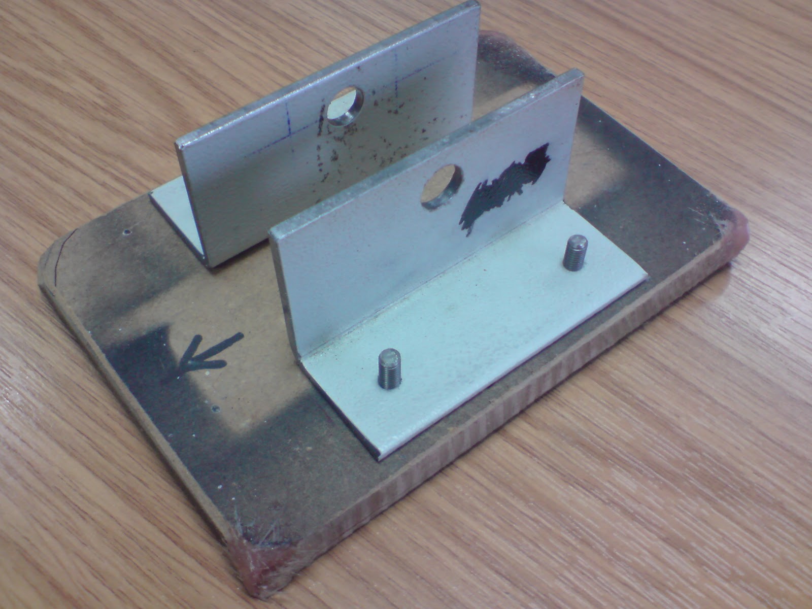
I had to mill off some of the angles base for clearance for the washers
Have now sprayed [with two coats] up the side curved detail panels in white :)
In this picture I have sprayed the curved panel detail white and with a coat of clear spray, also painted the screws using Humbrol gloss No.22 paint.


Corsham sci-fi family fun day, April 28th 2012


Corsham sci-fi family fun day
 April 28th 2012

Not long now   :)

I have been to this event, twice now and ALL the family (including the wife) enjoyed themselves!
If your into Sci-Fi then make this an event to go too. There is lot's to see and do, famous people from film & TV to see, stalls, shops etc.

There are also lots of costumed characters to see, Dr Who & Daleks, both old and new, Alien's & Colonial Marines, Predators, Stormtroopers, Darth Vader, Boba Fett and lots others.


So check out the web-site for who's attending and more :)

March 22, 2012

Centre Foot - Mark 2.6

Drilled another hole in the opposite side panel, that will be hidden by curved detail panel. So that long nose pliers can hold the nut when tightening the bolt up. Works OK, so next, the top panel can be glued in place.
Enlarged the second ankle hole in the angle for the centre leg bolt. This will help with aligning it up. Then  I gave the exposed angle a coat of primer. Primed panels lightly sanded before applying wood filler where needed.
Extra wood filler applied

Brian in development [where I do most of my work] noticed that my flat faced drill bit needed sharpening, so he re-sharpened it! Thanks :) So back in work today and more 'chain drilling' out the base with holes. Then used a Milling cutter in the Piller drill and used it to mill the inside edges flat.
Tested wheel swing diameter, and the lower plate frame needs some more trimmed off.
Here's a picture showing the protrusion of the wheel out of the bottom, so far.
And here's an 'all-together' picture [minums 

March 16, 2012

Centre Foot - Mark 2.5

Assembled the angle plates, with a spare bush and the carboard template. I then offered up the MDF wheel base and marked the threaded hole positions onto it. Next was to drill the four holes Dia 6.0 clearance holes and counter-sunk them into the wood base.


Measured up top strips of wood and angle pieces that will fit either side of the angle brackets, for foot shell.


Glued one in place with P40. Applied wood filler to gaps. But when working on it the next day, I applied to much pressure to it by mistake, and it popped off, see pic below.
Drilled a dia 16mm hole, for the ankle bolt to fit through.


Whilst test fitting the wheel board with angle brackets inside the shell, the top strip I fitted, broke off. This was due to the angles now being too high. And this was because I'd filed the edges off the board, making it sit higher up inside. So milled some height off the angle to sit flush, just below where the top strip will fit.


Found some 'U' section aluminium that I can mill down and use as the foot shell's groove.
Cut it down to length, then made cut outs to fit over lips front and rear. Next was to file down the  'U'  sections sides so it would fit the groove.


I removed two of the wood fill in side pieces. I need to make up a full length piece. Finished off the night by sanding the filler on the second curve detail.


Top Aluminium Plate, Angle brackets and Wheel board, inside foot shell.

March 13, 2012

Centre Foot - Mark 2.4


Applied P40 resin to curve detail of side panel on centre foot. Once set, I then applied wood filler.
  • Ground the 4 screws down to size to secure the second side panel to the foot shell.
  • Sourced an M10 Hex socket bolt.
That I'll be able to use for bolting the centre leg to foot with. Just needed to be shortened down to correct length to fit in the Foot shell.

Bolt now shortened
Am also drawing up some special tab style washers to locate the M10 nut in place, therefore only requireing one hole to be made in the foot shell.


Cut out the second aluminium strip. This one will be for the rear of the foot shell.
Foot strips, left one has it's angle already applied, right one yet to be done.
Both need  to be cut to finished length
Test assembled the ankle bracket, leg, foot shell again.


This time to make up a cardboard template up for the wheel board. The angle bracket(s) picture above, will be screwed onto the board and then the wheel(s) will be fixed onto it as well.


Drilled and tapped (Two) holes in one of the angles, for fixing to wheel board.


The original bolt holes in the angle also needed increasing slightly, as the bolt thread was a little over size, compared to the original M10 studding I had.


Wheel board, now cut to size (with cardboard template next to it).
still needs a lot of work doing to it :)

March 10, 2012

Centre Foot - Mark 2.3

Centre Leg & Foot Shell, mock-up....looks goooooood!

Got some more work done. I drilled out the slots in the side panel detail and filed then square......ish. I then cut and glued a piece of board behind them. Applied some PVA glue to the edges as this hardens the wood up. Once dried, I applied some wood filler inside the slots as the board had split away from the centre strip.
Next I started on applying wood filler to create the slop on side panel. Once this was drying, I marked the position of the main panel onto the side of the foot shell. Then drilled clearanced, countersunk holes for the screws. I then drilled a smaller hole in the foot shell so as not to split the wood. These screws were also ground down to correct length.
Whilst this was all drying, I started looking at the bolt location and channel section of foot shell.

The Foot shell is not the correct height. This I found out after I had glued up the sides :(.
This is something I can live with and can work around. It's not that must shorter than it should be, but still.
I was looking at using M10 nuts and studding, but now means the hole(s) needed to fit a socket through will put a hole in the wrong place. I've therefor thought of using M10 hexagon socket screws/bolts. These I can source and the hole required will only need to be around the diameter for the bolt head.
I made up a cardboard template and fitted nuts and studding I had into the foot shell. I couldn't resist a mock-up pic above :)

March 09, 2012

Centre Foot - Mark 2.2

Marked up and drilled one hole 9.6mm dia, through angle plates. Drilled second angle plate.
Next: need to mark up and drill fixing holes to mount angle onto base for wheel(s) to be mounted underneath.

Applied more wood filler to curved detail. Sanded profile smooth. Applied PVA glue to cut edges of the hardboard, this seals the wood and helps to stop the spray from being soaked up.
Applied more wood filler to foot shell, cover the grain. Sanded smooth.
Started on seconed curve detail.

Base - blanking 1.2


Base insert. Cut out & filed it to fit in the gap. I used a simple cardboard template.


Now glued into place. Just needs some extra filler and sanding etc.

March 07, 2012

Centre Foot - Mark 2.1


Used a piece of board (not shown), marked with straight lines & right angles. Mixed up some P40 resin and glued two pieces each together along there edge. Lined the two pieces along the lines so they are 'square' to each other. This was easier than attempting to glue all four sides at once.
 wood filler to shell face to cover the grain
Next was to work on the sides. Marked up and then cut out the details. Cut a spacer block to angle panel face. Finished the wood cutting & shaping for one side. Started to apply wood filler to shell face to cover the grain. 


Wood filler applied to create slope. Uneven edges in slots filled in also.

Had to make a new wedge spacer. Then started to apply P40 resin to curve.
Applied wood filler to panel slope, touched in the two slot edges to make square.   
The Centre Foot Sheel, so far.....


Next I glued the two sections together, again using P40 resin. The picture above shows the side panel screw temporarily into place. This will cover the ankle bolt hole beneath (hole not made yet). Also shown is one of the aluminium strips that will go on the front/rear of the foot shell.

March 02, 2012

Painting Main Leg - UPDATE


Main Leg:

Next I painted silver groove around the leg &then the inside edges of shoulder stabiliser sockets, as these would still be seen when the plate is fitted.


March 01, 2012

Centre Foot - Mark 2.0

Found I was going to have a few problems with the metal build, so decided to go back to a more simpler idea of a wood version. This also means I'll be to build more at home :)


Cut out the sides and have chamfered the leading edges.

Painting parts...

Restraining Bolt - weathered effect:
After looking at other builds, I decided to weather my restraining bolt and also add some detail to it. Used black paint and applied with a small brush.
I used Humbrol black, that I bought years ago and used for painting up my Stormtrooper helmet.
When dry, on the aluminium, it still looks wet like oil.


Shoulder Hub - weathered effect:
Applied black paint to the inner recesses.