
Showing posts with label Plasti-Kote Silver. Show all posts

March 09, 2024

Treadwell WED-15-77: Part 25

 March 2024

I started this build back in November 2021:
Link to part 1 and now it’s coming to be completed this year 2024.

I will be creating a page viewable via the top tabs (PC) or via the drop down menu on your phones which will have links and photos to these posts.

This month:
  • Spray Painting
  • 3D printing
  • Rubber track moulding (YouTube)
  • Re-assembling
  • Electrical installation and testing
Painting the base:
I stripped the base of everything not made of wood lol, a pain, but it means I don't have extra weight and also I don't have to worry about something getting knocked by accident.
I then masked off the paint I wanted to keep and sprayed the bare wood with primer.

Some of the area's not sprayed are because these are going to have panels covering them, as painting neatly wouldn't of been easy. Here’s the masked off areas, spray primer work.


Once happy with the primer, I applied the blue paint.

A clear coat was going to be applied once dried, but the order didn't arrive, so this will have to be done at a later date.

Painting extras:
The one remaining wheel, plus the front wheel brackets and the lid supports, all got a coat of silver (not Plasti-kote) paint.


Also sprayed up were these missed wheel bushes and the mast base support.
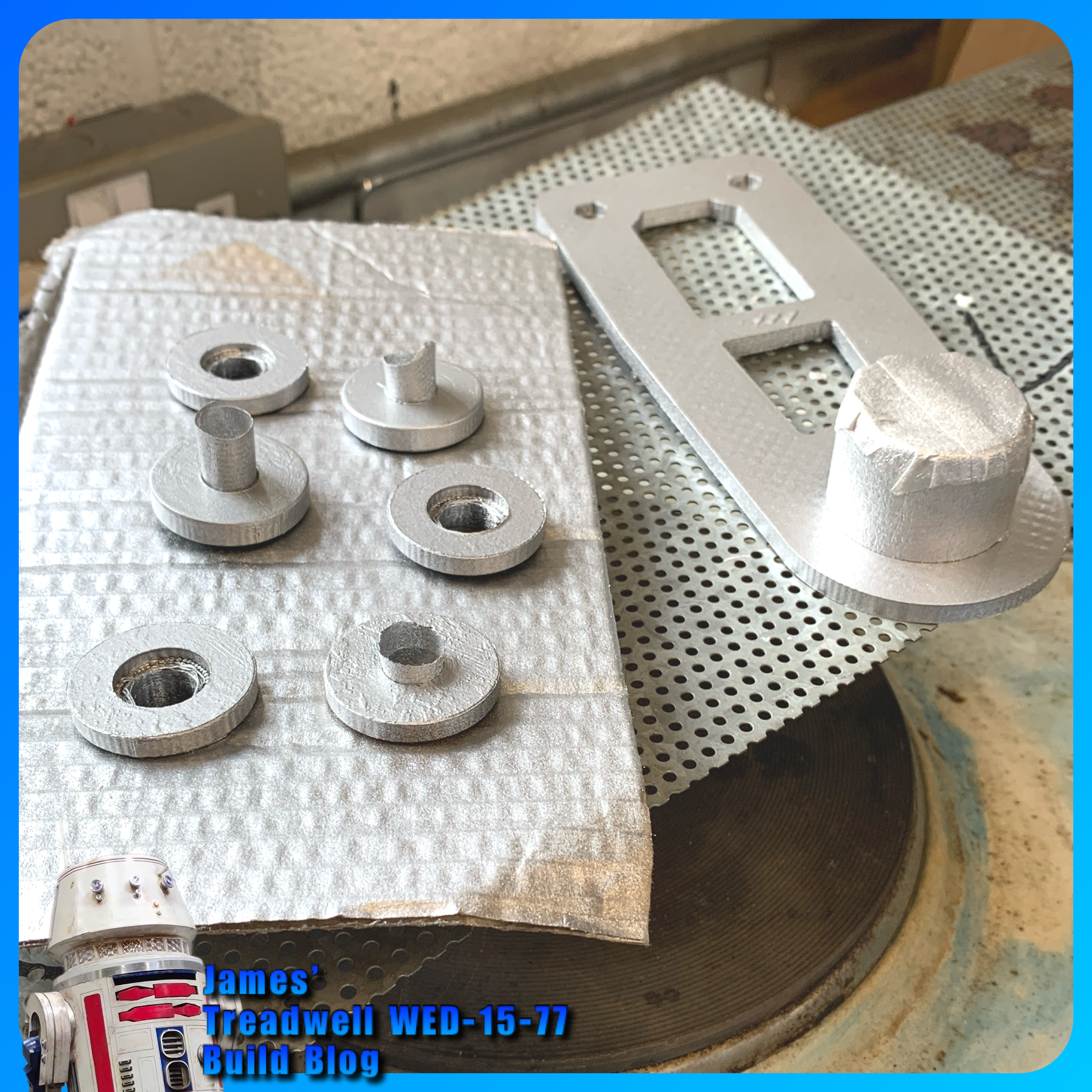

Servo connections: block plug or just loose.
(Planned work, now next month’s schedule)

Tracks:
Ordered a single batch of two part mix of the mould mixture, to create the tracks with. I thought, if I need more, I can buy more.
The new track mould I printed last month didn’t print out very good (lifted off bed so not flat). Later, after a few failed prints, I found that the nozzle wasn’t as clean inside as I had thought, even with hot and cold pulls. So I didn’t reprint it as I already had two moulds anyway.

I used my original moulds (green filament) ones. Dusted with talcum powder as a release agent. I had seen this done, but don't think it works too well in this application lol. Read on for what I eventually used.

Here are the track moulding in progress. I made a video of this now up on my YouTube channel.

In the video, the track that couldn’t come out of the end of the mould was due to the filament that didn’t have support and had sagged, so the fluid mix was absorbed into it, bonding it together.

This part of the mould has been removed (cut out) and sealed with superglue.
Only one of the two mouldings poured, cured, bit disappointing really and don’t know why?? = after a few more attempts, I figured out that the mixture wasn't mixed properly and so hadn't cured properly.

Here is the joining plate with two ends, of already moulded track in position. Mixing up and pouring into this, joining plate, joins these together.

The poured join. Inside doesn't look great, but that's not important.

This was another poured moulded section.

Here is all the track made so far, these will all be joined when the second delivery of mix arrives.

The mixing and moulding process improved as I went along. I now have enough moulded to complete one full set of tracks, but will have to order a second batch of mixture.

Guide teeth:
I did have a go at moulding a ‘guide tooth’ onto a piece of track.
This first attempt, didn't work. The rubber didn't bond to the back of the track like it does with the joining sections, as I had expected. Once released from it's mould, the thickness (height) effected it's ability to flex with the thinner track when moving over (around) the drive wheels at both ends. So am going to have to look at something else or another mould idea.

Glue:
I did find and test out some special loctite glue which can be used on rubber.

This seems to work, still testing, but this could be what I need.

Mould Release:
Here’s the mould release agent I used, found a can in work:

The following picture was the last of the mix I had to bond together two pieces of the track. The rest went into one and a half track mould.

Video of the track coming out of the mould on my YouTube channel.

Test laying the track on the wheels:


Re-assembly:
As the build progressed, little snags appeared. One being my choice to use nylock nuts and washers to secure the front wheel brackets. The protrusion restricted the required clearance and they would catch on the inside face of the wheel.

Plus i needed to trim the bolts down in length, and use normal nuts with thread lock.

Not to waste the nylock’s, these were swapped over on the mast base support bracket.

Electrical:
I needed to move the power switch to the outside panel for ease access. This meant unsoldering the switch on the panel, adding a new plug connection and fitting the switch into its new location.

I drilled a dia 20 hole and fitted the switch just behind the mesh panel.

I finished off adding the power cable from the battery to the board, via the switch. And (test) connected up to the battery……

…..we have lights on the components.

Will the next Blog post be the final one…..????

June 29, 2023

Treadwell WED-15 droid build : Part 19 - wheels/body/tracks

 
3D printing:
Printed off the other three drive wheels, see last post. These green items are printed in PLA+ filament, l ordered to try, instead of standard PLA , for work.

Next up was to print off the idling wheels (image below). Each one I managed to get down to 11hrs per whole wheel. Allowing the 3D printer to be free for work, these were an overnight/weekend print run.

I had a look for suitable fixings for the idlers, and found some old recycled furniture bolts that where just the right length.

So before printing off the wheels, I made an adjustment to allow the bolt head to be recessed flush with the outside face of the wheel. I also drew up and printed off some bushes for the bolts. The bushes help space the wheel away from the body, as well as threading onto the bolt, helping to keep it located. I repurposed and added a soft washer to help with possible friction.

I then sprayed these up with primer, and eventually with silver paint.


The little Details:

Eye servo lead:
The lead for the servo eye movement, needed a sleeve to cover it up, also adding some strength support to it as well. I had kept some thin walled black tubing that was just wide enough for the lead (minus its plug) to slide through.

I added a cable tie to the inside of the eye opening, pull prevention, and then drilled a hole in the upper neck for it to pass through. I then refitted the plug to connect with the appropriate servo lead.

Eye pivot tube:
To stop ‘wiggle’ from the eye supports arms, I drilled holes through into the pivot tube, and secured. This helps prevent the eyes from independent movement when the servo moves them. It was only slight, but it annoyed me lol.

I recently bought off eBay:
STAR WARS MOVIE FORCE ATTAX SERIES  2 BASE / BASIC CARD no19: Treadwell Droid.

Straight knurls:
On closer inspection of the card, I noticed the straight knurled rings around the mast. Don’t know how I missed this detail?!?!?

So I made a copy of the 3D mast model and modified it to include these details. As I wasn’t going to reprint the whole mast again, I decided to just print off the details as rings, with a thin wall thickness, and these would be glued onto the masts diameters. Better than nothing lol. They don’t look too bad actually. The first ring I glued into place.....then thought.....it would be easier to spray them up first before gluing them in place lol oh well.
Sanded back the paint for a better surface to glue to.


For the others, I just cut them to the correct length [diameter], and primed/sprayed them silver. The mast had to have it's paint removed where these were going to be glued.

Base Antenna:
I had drawn this up a few months back but was waiting on the chance I found any better detailed pictures. No such luck, but the trading card did help, so this was the next piece to be 3D printed. 
The idea is based on a split spherical design, with a ‘bolt’ that holds the two ridged semi-circular hemispheres together with the option to adjust the angle.
Filler primer applied.


The 3D version doesn't do this lol, it just looks like it would, I did add a screw location for detail. Lastly I printed off a backing washer to secure to the inside of the lid panel.

The rear lid panel has now had it's inner panel, cut out and glued/clamped in place. This is to give it strength, but also alignment with the panel supports.

Painting & weathering:
I started to apply the acrylic burnt umber and yellow ochre that I used on R5 all those years ago, starting with the mast.

I drilled holes in the arms and mast to accept the wires and tubes that would 'operate' them.

Tracks:
Searching since last post with no luck..... then I came across YouTube videos of model makers making their own tracks. This gave me the idea to use the 3D model I'd created for the tracks and converted them into a mold. I ordered a small batch of Mouldcraft Black Poly Flex 60 Shore Fast Cure 120g Polyurethane Casting Rubber, as a tester to see if I could mold/make my own.

I designed the mold in two half's, the front (outer tread) and rear (inner) section.

I also 3D printed off a joining mold. This was so that the sections of tread could be joined together...... hopefully.

I tested a small batch of the 60 shore and it was to sticky after it had cured, no way it would of stood up to actual track movement lol.


Test sample, binned along with the mold.
So I ordered some 85 shore, let's hope this is better.

Drive wheels:
As mentioned above, in my design haste, I'd forgotten to add the step detail to the front face. So I updated the 3D stl file and then printed off a set of disc's to fit onto the front of the wheels. These were glued in place and then all had primer and then sprayed in Chrome, which dulled to a nice Aluminium look once clear coat was applied.


With our South West Builders Day event approaching, I needed some axle locations for the drive wheels. These will just be to help hold them in place.

Base:
Another BIG annoyance is that on the original magazine article it clearly shows that as well as the upper front angle, there is also a lower one as well. This can also be seen in the rear image seen in the deleted scenes. This detail is missing from the builders own blueprints unfortunately.

Don't know if I can modify the base to suit..... it could be a lot of work, something to look into though.

Tracks pt2:
This last week has been last minute finishing off details as best I can before Sunday’s event.
I wanted tracks but there wasn’t going to be enough time, so I resorted to rubber mats id rescued in work a few months back. These were cut to width and once the ends were trimmed flush, I superglued them together.

These were joined in a loop with a staggered join.
The finished track loop turned out great.

Once dried, I fitted them onto the wheels.
Really happy with this, even if they are just display tracks..... more updates next month.

December 18, 2021

R5-D4 Carbon Frozen progress


November:

I had seen someone add paint to a mixture of PVA glue, this worked great!!
Perhaps it was the paint I used, but it made the glue lumpy, which added to the textured effect. I mixed up a few batches to not waste, but also to see if it would actually dry 😄.

…..which it eventually did, took a bit longer though.


Project paused till December:
I dug out this project and checked that the glue had now fully dried, before I applied the same paint over the exposed areas.
It just needs a few more coats.

#carbonfreezing #funkopop #R5D4