June 27, 2014

Outer Feet - New foot internal frame work 1.6

For my Wood internal wheel frame, I used T-nuts to be able to clamp the leg ankle to the foot internal. This was a great idea as it ment I didn't have to (somehow) reach inside and try to secure the bolt to the nut.

Now I have metal frame work, this requires I get a nut welded to the back face.
Here is the finished frame, just need cleaning up the weld splatter. Thanks Dave, great work!
R5D4 outer foot

R5D4 outer foot
Aluminium angle and bolts can now be removed.
I will need to cover/fill/block up the threaded holes visible inside the side channel plates.

I also needed to re-drill a hole location for the lower aluminium channel plate.
One was a new hole due to the location of the new metal frame internals and the old hole would need to be blocked up. So I decided to just make up a new strip as the old version I wasn't to happy with how it looked or would of looked with the blocked hole.
So I drilled & countersunk two new holes.
Outer Foot shell
Secured with these hex socket countersunk bolts off eBay :)

Sorted out the axel bolt holes and reduced the brass motor bolt bush's my 1.6mm.
This helped alignment of the belt with the wheel more.
R5D4 foot motor
Next up is to fix the front caster back on. This is a stabiliser to keep the foot level.

Measured up the inside, this is bacause the metal flexed a bit when it was welded.
These are just gude measurements ;-) lol
R5D4 foot drive

R5D4 foot drive
Next is to fit the front caster on, then it's on with frame work for Outer Foot No2.

June 23, 2014

Outer Feet - New foot internal frame work 1.5

Back in work to drill the holes. The three 5mm dia clearance holes for the Motor plus a centre drill point to help line up the other plate. Then using a drill and a boring tool, I got to work on opening out the hole to fit the back end of the Motor through.

Well, the hole alignment between the two main plates for the wheel axel, were off......only a bit but enough for the belt to be so tight it tipped the axel and the other end wouldn't fit through the hole in the other plate! The hole in the side plate for the back end of the motor to fit through, helped align it, so I opened up the holes a bit.

I got Dave in work to weld up the frame.

When I got home Friday, my two axel bolts had come. Once I'd fitted it all together, it looked like this.
R5D4 - Outer Feet Motor Assy

R5D4 - Outer Feet Motor Assy

R5-D4 Outer Feet Motor Assy
The last picture (above) also has the first channel wall piece. These wont be welded on (for now) as I'll need to sort out clamping of the leg and also how best to support the Outer Foot shell to the internal motor/wheel frame.

Next job then was to locate the first channel wall piece. I drilled and tapped into the Steel frame & the channel wall piece.
R5D4 Outer Feet

To be continued......

June 19, 2014

Outer Feet - New foot internal frame work 1.4

I had two choices:
  1. To modify the internal wood frame work to accept the new wheel and motor arrangment. Wood/Metal hybrid?
  2. To build a new metal 'frame' based on design's already used by other builders?
Neither is a quick solution.
Am going to go with new metal internal frame works. Going to follow, attempt to follow, a now tried an tested method of assembling  a 'flat pack style' frame work.

Outer Foot Shell - R5D4

For more details, see Astromech.net.

So I ordered some metal plate as a starting point. 300x300x3mm thick.

Outer Foot R5-D4
Above pic is sheet 1 of the two bought. I then made a carboard template and worked out best position for the wheel and fixing bolts.

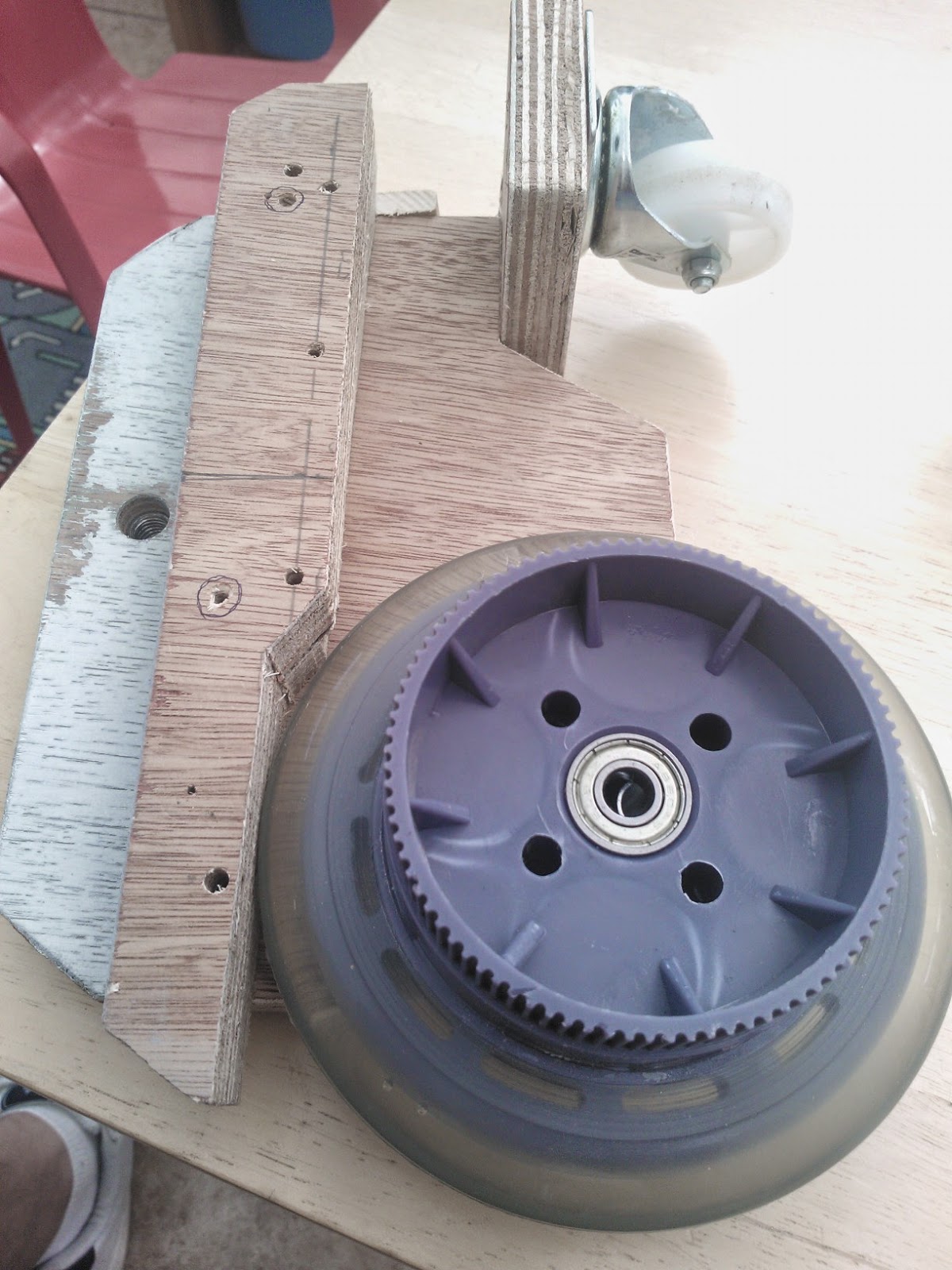
I needed some spacers to fit between the wheels and the side plates.
So turned some up out of Brass bar.
I didn't fancy replacing these at a later date and the bar was to hand.
To reduce some of it's weight I turned a step diameter to produced 'flanged' ends.

Wheel spacers
M8 x 80mm long bolts are ordered for the main wheel's.

Next I got out my (my Dad's) angle grinder, that I 'borrowed/was lent' about 15 years ago lol, and got to work cutting out the sections. For my first attempt's at cutting, and comments I've recieved, I didn't do a bad job of cutting straight edges!

R5D4 feet


In work I used the piller drill to drill accuratly the two holes for the main wheel bolt.

I used the works guillotine to cut two strips which will be welded across the top,
to the sides to form a box section.

After measuring the distance between the wheel and gear on the motor, I marked an arc from the centre of the wheel bolt. This helped me to determin the best position for the motor to fit inside my Foot Sheel. As there's not much room. I roughly marked an opening area on the inside face of the foot shell and cut it out.
R5D4 Feet

R5D4 foot shell

R5D4 wheel & motor

R5D4 wheel & motor
Next is to drill holes, but that's a 'back in work' job......

June 09, 2014

Outer Feet - motorisation is on its way 1.3

Well, the wheels did NOT arrive last week as I had hoped, so was refunded via eBay. Some more were found and were soon be ordered.

Scooter wheels link

My Son was just as excited they had come as I was. So we both headed out to the garage to work on removing the 'brake drums' which we won't be needing.

These are held in place with four metal pins. I opened up the vice jaws and rested the wheels on the opening. We then got to work with a hammer and screwdriver to hit the pins out from the other side.
R5-D4's Outer foot wheel to motor upgrade

The four pins can be seen in image above.

Here is what I am faced with next though....
R5-D4's Outer foot wheel to motor upgrade

R5-D4's Outer foot wheel to motor upgrade
Apart from the increase thickness, they are also slightly larger diameter than the old scooter wheels, so internal upgrade WILL be required. Design process engaged!

I also thought at first that my belts were too short as the motor was quite close to the wheel, but on second thoughts this might not be a bad thing as space is limited inside and also the position of the motor means it has to be fitted/covered by the battery box once all installed.