

Have been working on:
- Power
- Wheels - drive axles
- Axle bushes
- Polypropylene washers
- Electrical/electronics
- Bodywork
- History…….wait what???
- Details
- Testing, Testing, 1, 2, 3…..
After the last post, I knew I needed a proper to-do-list. Most of it is not directly related, more reminders lol.
Power:
Going to go with a single 12v battery for now, borrowed from R5 for now.

Wheels & Drive Axles:
machine up some proper axles for the two drive wheels. This will connect to the motor via a coupler that I machined up myself.

Next up was to machine up 1 of 2 drive axle couplings.
 |
| Coupler being machined for M5 grub screw |
The actual wheel bushes and location end pieces for the axles fitting into the wheel, needed to be slightly modified and re 3Dprinted.
Axle Bushes:
Machined up the rest of the Brass bushes that are press fitted into the wood side panels. I reoriented them so that the lipped edges are inside the frame.
The two main drive wheel bushes are slightly longer to take up the space between the side panels and the couplers. Bottom left rear wheel doesn’t have a coupler or motor fitted at time of picture being taken.
 |
| Test fitting of the wheels, temp tracks and motor no1, to see if it has enough torque to drive |
Polypropylene washers:
3D printed off a load for both outside and inside.
The axles are then locked in place with M8 Nylon locking nuts.
Electrical/Electronics:
- Ordered a Sabertooth speed controller from the Robotshop. PayPal allows you to pay in three monthly instalments, very handy.
- Ordered some 12 gauge red & black cable.
- Ordered a 12v geared motor & on testing, ordered a second one.
 |
| Sabertooth speed controller |
Bodywork:
Tapped up and filled in the front and rear gaps for the cut angled faces. I used glass fibre filler, P40.
 |
| P40 glass fibre body filler |
Then applied P38 body filler over the face.
Sanded smooth, ready for more paint.
 |
| P38 filler applied, Pre-sanding |
Next up was the side axle cover plates.
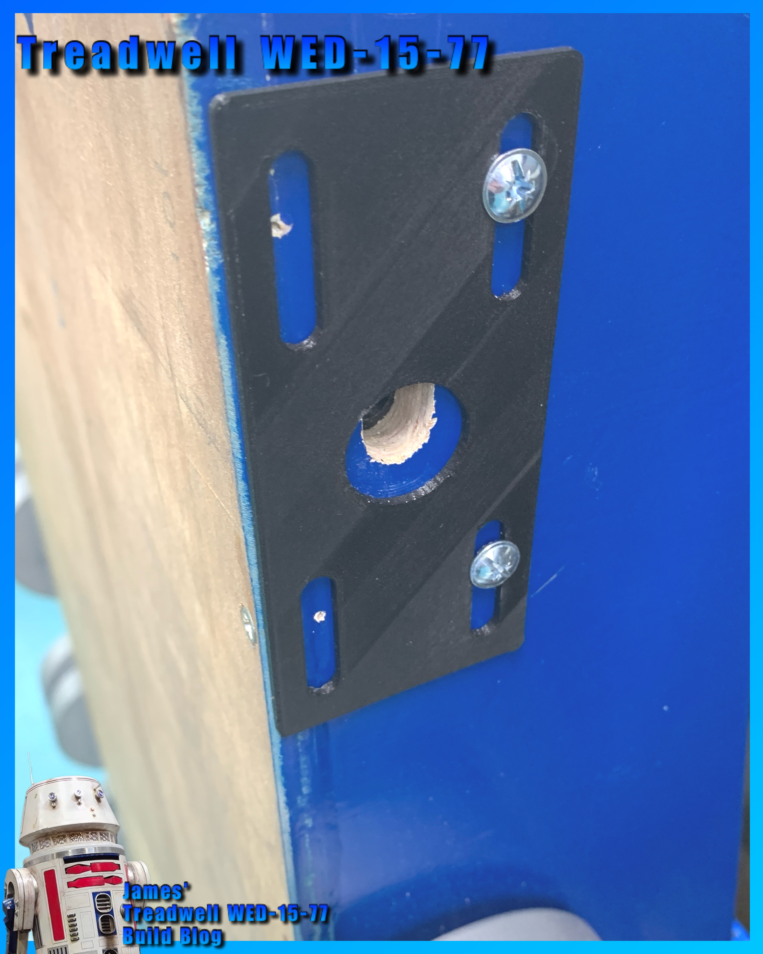
These I drew up in CAD. The inner bracket is my own design. It is also the wheel axle guide. Got some M5 flanged head bolts coming, to secure both axle plates.
(Temporary bolts fitted in pre picture)
History:
Have been trying to find the original electronics used, speed controllers (x2 off). These wouldn’t of been your modern electronics speed controllers (ESC’s), but Transistorised versions!
Still trying to track the actual ones used etc.
Details:
I noticed that the antenna has a black (possibly rubber) end piece, before the aerial rod. So I quickly masked it off and sprayed it black.

Testing, Testing, 1, 2, 3…..
I wanted to know if the new motor had what it needed to drive the tracks. So I fitted the wheels as best I could, some didn’t have some of the bushes or proper securing nuts. Added the ‘display’ tracks I made last year for display purposes. Hooked up the battery and connected the motor.
Video link.
Not the best and didn’t have full control , but it was just to test it worked.
Next up:
- is fitting the new motor and brackets, when they come.
- Installing the electrical components.
- Machine up another coupler.
- Machine up two final axles.
- Test fitting everything inc mast and head.
Finally, I need to make the new tracks, but need to purchase the materials first.
No comments:
Post a Comment