May 31, 2013

R5-D4's Head - 2.7 - 'I love it when a plan comes together'

As the title suggests, those imortal words spoken by Hannibal Smith, of the original A-Team, tv show, ''I love it when a plan comes together''  ;)

Not being able to work on R5's Dome for the last two days has been frustrating LOL :D

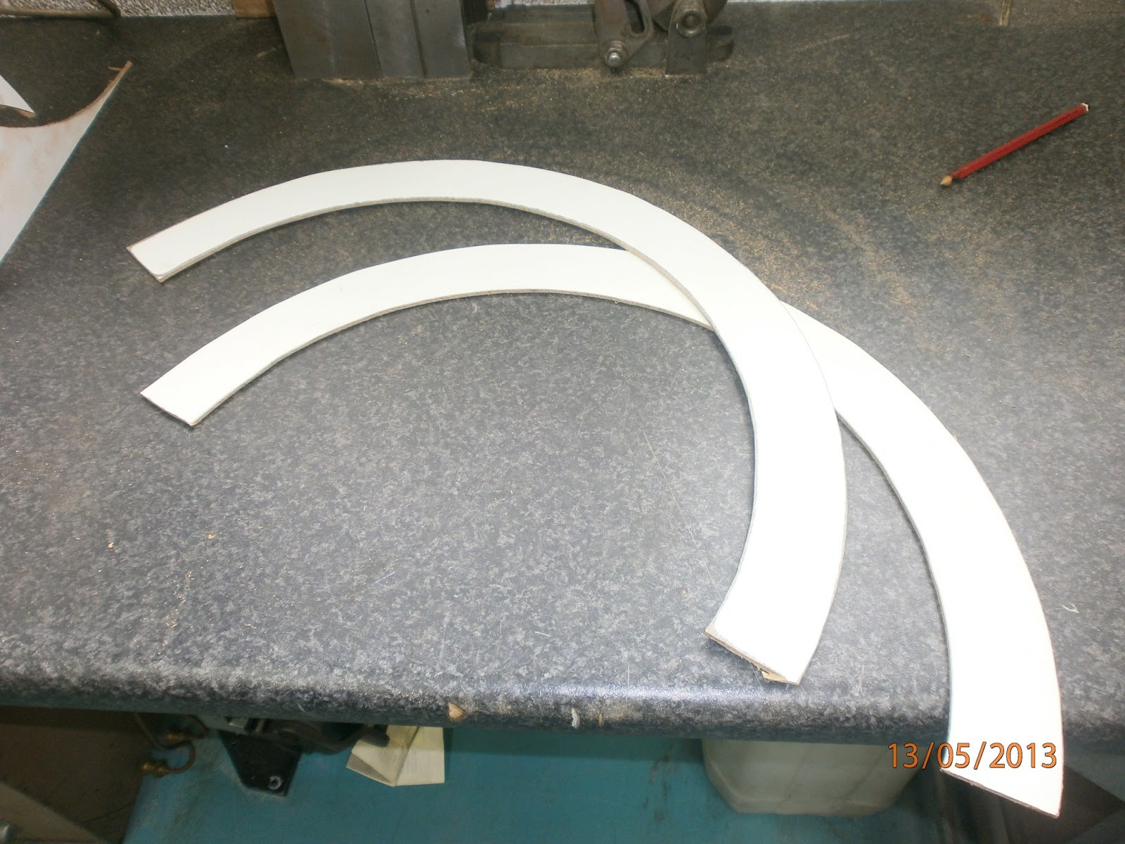
So this morning I loaded the three main parts for R5's Dome and got into work early [also no traffic as kids & parents on half term]. I needed to notch out the 'lower ring' to fit over the frame uprights. These also had a little excess material trimmed off. This is so it sits as low as possible, for securing to the frame uprights and also onto the Dome itself.


May 29, 2013

R5'D4's Eyes - Main Eye No.3 & Upper Eye

So last Friday I finished off Main Eye No.3, after work. All of 10mins. Having all three Main Eyes fitted with the Spyholes, looks great.

Machined up the Upper Eye [the long one] today. Threaded the rear with an M5 thread, for fitting and then inserted a 'star' washer into the end to add effect.
This took about half an hour all in to complete.
The washer on the end is to retain the Eye once fitted.

R5-D4's Head - 2.6

I drew up in CAD, an upper and lower rings. These I am hoping to use to screw the two main dome panels to, to help retain their curve and shape. As my first attempt at keeping them curved failed.

Then Saturday I marked up and cut out the upper ring [still a disc at the moment]. Angled the Jigsaw to it's pre-set angle of 15 degs, close enough to what I wanted ;). I've countersunk and then screwed the panel onto the upper ring, starting with the centre and working alterntivly either side along the edge, to prevent the wood from splitting.This was last night and it was still holding this morning lol. So here are some pics so far.
Screwing the panel down.
you can see by looking at the ends that the hardboard doesn't like being bent :D
I'll be cutting out the lower ring today. This piece is definatly needed!!

I need to next mark on it the position of the opening for the Motivator dome panel and also the Antenna. As am thinking that this could be bolted onto it to secure it (??)

May 24, 2013

R5-D4's Head 2.5 - Main Dome/head work

Thursday morning I got on with cutting out the two main pieces of R5's Dome/head. I tried joining them together [see pic below], but when I applied the strap to aid shaping, the wood split :(. Luckyly not to much damage, all glued back together.


So it's not onto idea No2 [that I've seen done before].

R5-D4's Eyes - update

Finished machining up the first two Main Eyes. Machined out of aluminium. And fitted with the 'Spyholes'.


The first two completed
Just need to machine up Eye No.3

May 23, 2013

R5-D4's - Eyes

WOW that was quick! The 'spyholes' arrived the very next day [ebay]. So on now with machining up the eyes for them to fit into.

May 22, 2013

R5-D4's Head 2.4 - marking/cutting/fitting

So last Friday, I started on bonded the rear dome box pieces together with p40 resin. Cut side pieces for side box no1. Whilst this was setting I did some sanding of the wood filler on the dome rim.

I then decided to take off the upper curve, to be replaced with a longer piece. Then I realised that I had used the lower curve template! The upper curve is larger because the dome has a different angle.
The dome boxes being prepped for bonding
Saturday evening, I marked out on hardboard, using 1:1 scale paper templates, the correct upper curve in two pieces, [not four as before] for the dome itself. Worked out & Marked recess boxes & 'eyes' positions etc.

I positioned the dome top plate onto the hardboard and also the second upper curve. Managed to fit it all onto the one sheet. Then started to cut all the pieces out.

And then fitted the new upper curves into place.....
The curve still wouldn't keep it's shape, so I had to add the extra 'support' pieces.
Pictures below, show the two upper curved pieces fitted and the new upper 'support' pieces fitted where needed to help keep the curve [circled in red]. What I should of done was made up 8 [eight] main support unit's spaced around the main ring, that way I wouldn't of had to bodge these in. Never mind, a lesson to anyone reading and following :).

Before fitting the 'upper' supports, the gaps show the curve is not keeping it's shape 

Wood filler also applied


After reading and following this post over on the Astromech.net forum R5-D4 option for my R2.0 buildI went looking for 'spy holes' for doors. Most were quiet expensive, well the larger ones were, i.e. 180 degree vision x3 off = nearly £15. But eventually I found some on Ebay, total £4.79.
R5-D4's three eyes
R5's Dome Eyes

May 16, 2013

R5-D4's Head 2.3 - curve problem and Dome boxes

Lunchtime yesterday, I only had time to cut out three of the four curve pieces I needed for the Upper section of the Dome. Available material, meant I had to reduced the length of curve, hence four instead of just two. But, I had problems with fixing the first one and restraining it in a curve, whilst the bonding resin set.
This was the result. Not happy with this, so am going to have to get some more board to cut curve to original length and re-do it. I needed to get some more anyway as I don't have enough for the rest of the dome. In the meantime, I started sanding the wood filler I'd applied.

Dome recess boxes:
I have been looking into how I am going to fix my Dome Rods that I made, years ago. These fit into three recessed areas, one either side and one at the dome rear. The side rods are the same the rear is different.

What I've done for the two 'side' rods is drill a hole through the top plate so the rod slides up thro, then they will be secured in place with M5 socket head screws. The centre rod, which goes at the rear of the dome, will have a pin in the top plate, and a screw up from the bottom. Well, that's the plan, watch this space lol.

All three rods were machined in two pieces.This was due to the amount of material protruding out of the Lathe's chuck. Especially when producing the straight knurl, as the material is not cut, but deformed. 

May 15, 2013

Bad Motivator - upgrade work in progress 2.0

Continuing on from previous post regarding my/R5's 'bad' motivator. I took apart the three main assembled pieces. I then had to remove a piece of molding that was going to be in the way :( I've kept it as I can re-attach it in a new place later.

Next I had to file a flat on/into the top dia, so that the 'heatsink' pad would sit flat. I then drilled a new hole where I wanted the 'coiled' piece to be. I need to make up a new circle piece to go on the stub, but this might not yet be seen, depends how much motivator I have sticking out of R5's head :)

So here's my work so far and the image I found for comparison.


It's not 100% accurate, but it's getting there and I'm a lot happier with how it's looking :)

May 14, 2013

Bad Motivator - upgrade work in progress

The other day, I found this really close up image of R5's 'bad' motivator.

And it got me thinking back to my original drawings and ideas of how mine should look like. I bought a great resin item when I saw others were using them to and thought about keeping it 'cannon' so to speak, with everyone else's.
R5-D4
My original sketch from zooming in on the TV screen, DVD paused :D
This is how mine looks, but am going to attempt to re-jig it to look like the above image.


http://r5-d4astromechdroid.blogspot.co.uk/2012/07/r5-d4s-motivator-13.html

R5-D4's Head - 2.2

So over the weekend I managed to get some more work done on R5's head. I had an issue with securing the two strips together. Wood glue would only hold one strip, then it would tear the other piece apart. Hence the clamp in the photo [see prev. post below]. I tried hot glue gun, but this did the same, even when applied to the wood ends. So I decided that I needed a more physical fix. I cut a thin piece of wood and drilled and screwed through the strips into it. Job done! :)

Next was to cut out the two lower curves. The paper template I had printed out to scale was taped down and the wood then cut with my Coping saw.

And here they are fitted. After two hours work last night lol.....don't ask ;D

I've pinned the curves in place and then used P40 resin to hold/fill gaps.
This is still a work in progress, still a long way to go :)

May 11, 2013

R5-D4's Head 1.2 - Frame & some skin build work

So this afternoon, I fitted the four main skeleton frame pieces and then made up four smaller ones to help support the lower curve pieces. These also support the main band and help retain the curve shape.

When I'd screwed them all on, I got the feeling of Darth Maul :D Been watching cartoon Clone Wars recently lol

Then I got to cutting out two lengths of wood to go round the 'recessed' area. I would recommend a single length, but the material I had was all that I had to work with.
 
Panels are held in place with panel pins and will get some resin applied at a later date. Once 100% happy with what I've done. Next I'll be cutting out and fitting the lower curved pieces.

May 10, 2013

R5-D4's Head 1.1 - Frame work

For the construction of R5's dome/head, I'll be using the:

Experimental R5D4 Head flatpack Rev4


This is on the Yahoo Astromechs Droid Builders Club file system.


So i Checked the paper template curve against my template skeleton frame. And it fits, close enough.

I've modified the frame to save on material & cutting. These will be screwed to the main disc. The originals were as long as the radius & the height of the dome main side wall. The skin templates will be transferred onto 3mm thick hardboard & cut out. The two pieces will then be glued together with a bridging plate.

Below are the first two skeleton frame pieces.


May 08, 2013

R5-D4's Head 1.0 - Started at last

Right, I've started on making R5's head.

A while back I bought a 'lazy susan' stype bearing. It's not the one used by most R2 builders, mainly because of the cost and availability! Mainly the cost, R5 is on a tight budget, just like I.A. were lol. This design will be based on a build that has been used by a fellow Astromech builder Emy R6 who has used this on all of his Droids!


So firstly I marked out the lower connection plate ring platform.

Then I needed to add a spacer to raise everything up.


Next comes the bearing, which is screwed onto the lower disc. The three bolts sticking up are my locating lugs for the upper ring.


Here is the lower plate that will support the 'Dome' ring.
 Here is the upper plate that will support the 'Dome'. Its had material cut out, to reduce weight.

 Upper dome ring fitted onto the lower ring.
 Above image shows the clearance. The spacer pad was needed for this purpose.

And here, I started to fit the lower edge of the dome. I measured the full height needed, but you can see that I have marked it into two. This is because the lower area is to be painted 'aluminium' when finished. I clamped the strip, then drilled and then used panel pins to secure the strip in length, I didn't have a long enough piece to do it in one full length. I will then use resin later to reinforce.