Showing posts with label speed controller. Show all posts

March 09, 2024

Treadwell WED-15-77: Part 25

 March 2024

I started this build back in November 2021:
Link to part 1 and now it’s coming to be completed this year 2024.

I will be creating a page viewable via the top tabs (PC) or via the drop down menu on your phones which will have links and photos to these posts.

This month:
  • Spray Painting
  • 3D printing
  • Rubber track moulding (YouTube)
  • Re-assembling
  • Electrical installation and testing
Painting the base:
I stripped the base of everything not made of wood lol, a pain, but it means I don't have extra weight and also I don't have to worry about something getting knocked by accident.
I then masked off the paint I wanted to keep and sprayed the bare wood with primer.

Some of the area's not sprayed are because these are going to have panels covering them, as painting neatly wouldn't of been easy. Here’s the masked off areas, spray primer work.


Once happy with the primer, I applied the blue paint.

A clear coat was going to be applied once dried, but the order didn't arrive, so this will have to be done at a later date.

Painting extras:
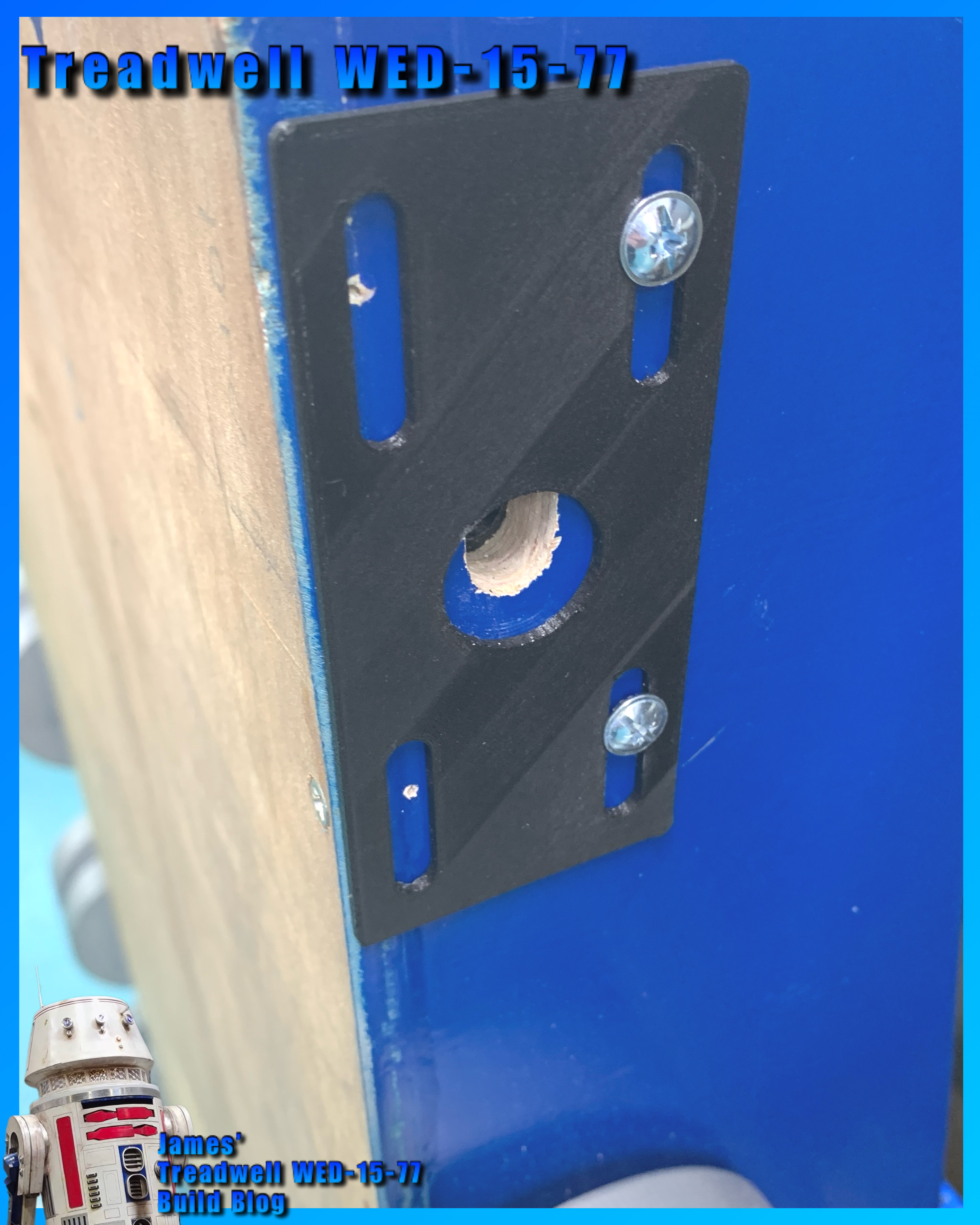
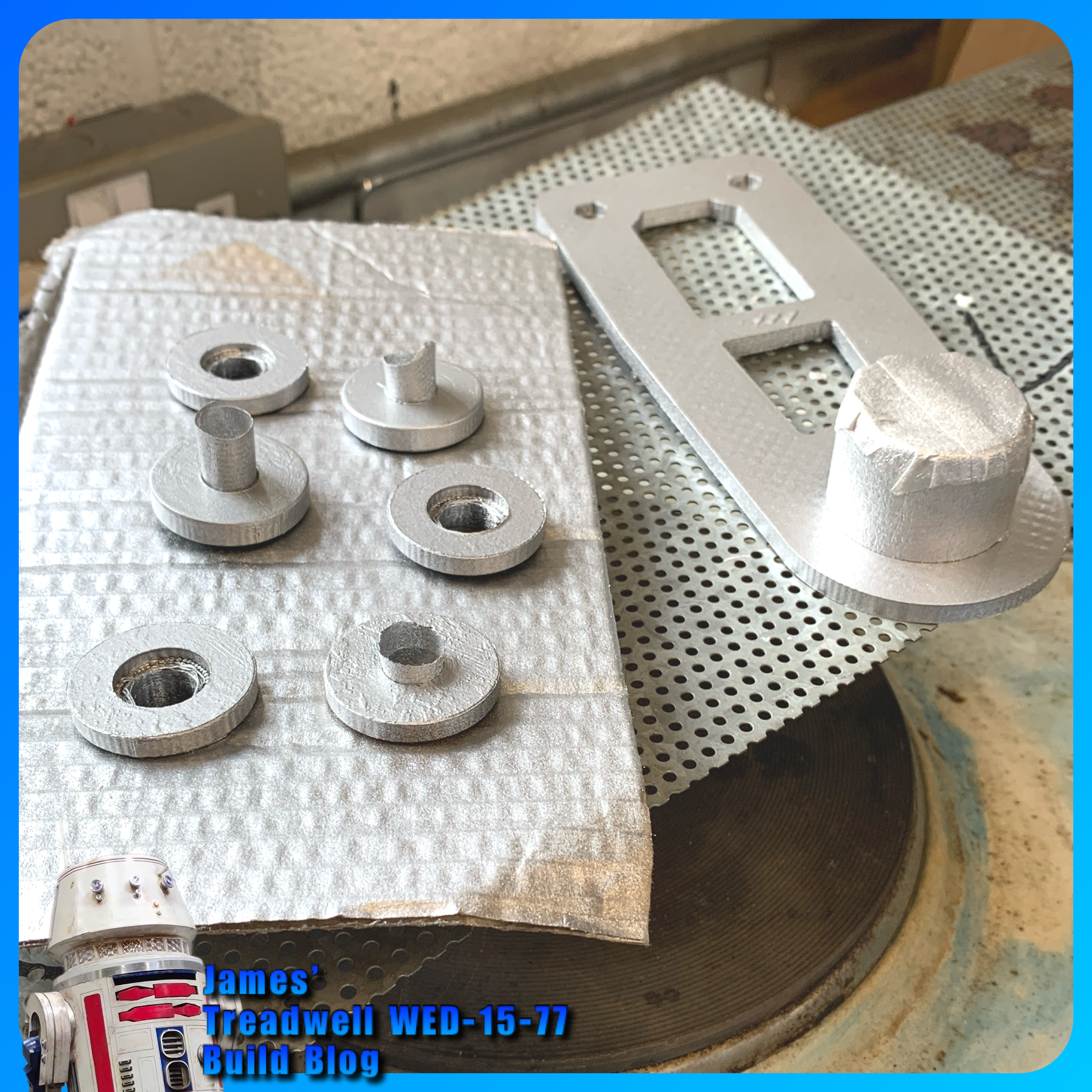
The one remaining wheel, plus the front wheel brackets and the lid supports, all got a coat of silver (not Plasti-kote) paint.


Also sprayed up were these missed wheel bushes and the mast base support.


Servo connections: block plug or just loose.
(Planned work, now next month’s schedule)

Tracks:
Ordered a single batch of two part mix of the mould mixture, to create the tracks with. I thought, if I need more, I can buy more.
The new track mould I printed last month didn’t print out very good (lifted off bed so not flat). Later, after a few failed prints, I found that the nozzle wasn’t as clean inside as I had thought, even with hot and cold pulls. So I didn’t reprint it as I already had two moulds anyway.

I used my original moulds (green filament) ones. Dusted with talcum powder as a release agent. I had seen this done, but don't think it works too well in this application lol. Read on for what I eventually used.

Here are the track moulding in progress. I made a video of this now up on my YouTube channel.

In the video, the track that couldn’t come out of the end of the mould was due to the filament that didn’t have support and had sagged, so the fluid mix was absorbed into it, bonding it together.

This part of the mould has been removed (cut out) and sealed with superglue.
Only one of the two mouldings poured, cured, bit disappointing really and don’t know why?? = after a few more attempts, I figured out that the mixture wasn't mixed properly and so hadn't cured properly.

Here is the joining plate with two ends, of already moulded track in position. Mixing up and pouring into this, joining plate, joins these together.

The poured join. Inside doesn't look great, but that's not important.

This was another poured moulded section.

Here is all the track made so far, these will all be joined when the second delivery of mix arrives.

The mixing and moulding process improved as I went along. I now have enough moulded to complete one full set of tracks, but will have to order a second batch of mixture.

Guide teeth:
I did have a go at moulding a ‘guide tooth’ onto a piece of track.
This first attempt, didn't work. The rubber didn't bond to the back of the track like it does with the joining sections, as I had expected. Once released from it's mould, the thickness (height) effected it's ability to flex with the thinner track when moving over (around) the drive wheels at both ends. So am going to have to look at something else or another mould idea.

Glue:
I did find and test out some special loctite glue which can be used on rubber.

This seems to work, still testing, but this could be what I need.

Mould Release:
Here’s the mould release agent I used, found a can in work:

The following picture was the last of the mix I had to bond together two pieces of the track. The rest went into one and a half track mould.

Video of the track coming out of the mould on my YouTube channel.

Test laying the track on the wheels:


Re-assembly:
As the build progressed, little snags appeared. One being my choice to use nylock nuts and washers to secure the front wheel brackets. The protrusion restricted the required clearance and they would catch on the inside face of the wheel.

Plus i needed to trim the bolts down in length, and use normal nuts with thread lock.

Not to waste the nylock’s, these were swapped over on the mast base support bracket.

Electrical:
I needed to move the power switch to the outside panel for ease access. This meant unsoldering the switch on the panel, adding a new plug connection and fitting the switch into its new location.

I drilled a dia 20 hole and fitted the switch just behind the mesh panel.

I finished off adding the power cable from the battery to the board, via the switch. And (test) connected up to the battery……

…..we have lights on the components.

Will the next Blog post be the final one…..????

February 03, 2024

Treadwell WED-15 droid build : Part 23 - woodwork, 3D printing, test drive


January into February 2024

Have been working on:
  • Power
  • Wheels - drive axles
  • Axle bushes
  • Polypropylene washers
  • Electrical/electronics
  • Bodywork
  • History…….wait what???
  • Details
  • Testing, Testing, 1, 2, 3…..
After the last post, I knew I needed a proper to-do-list. Most of it is not directly related, more reminders lol.

Power:
Going to go with a single 12v battery for now, borrowed from R5 for now.


Wheels & Drive Axles:
machine up some proper axles for the two drive wheels. This will connect to the motor via a coupler that I machined up myself.

Next up was to machine up 1 of 2 drive axle couplings.
Coupler being machined for M5 grub screw

The actual wheel bushes and location end pieces for the axles fitting into the wheel, needed to be slightly modified and re 3Dprinted.

Axle Bushes:
Machined up the rest of the Brass bushes that are press fitted into the wood side panels. I reoriented them so that the lipped edges are inside the frame.

The two main drive wheel bushes are slightly longer to take up the space between the side panels and the couplers. Bottom left rear wheel doesn’t have a coupler or motor fitted at time of picture being taken.
Test fitting of the wheels, temp tracks and motor no1,
to see if it has enough torque to drive

Polypropylene washers:
3D printed off a load for both outside and inside.

The axles are then locked in place with M8 Nylon locking nuts.

Electrical/Electronics:
  • Ordered a Sabertooth speed controller from the Robotshop. PayPal allows you to pay in three monthly instalments, very handy.
  • Ordered some 12 gauge red & black cable.
  • Ordered a 12v geared motor & on testing, ordered a second one.
Sabertooth speed controller

Bodywork:
Tapped up and filled in the front and rear gaps for the cut angled faces. I used glass fibre filler, P40. 
P40 glass fibre body filler

Then applied P38 body filler over the face.
Sanded smooth, ready for more paint.
P38 filler applied, Pre-sanding

Next up was the side axle cover plates.

These I drew up in CAD. The inner bracket is my own design. It is also the wheel axle guide. Got some M5 flanged head bolts coming, to secure both axle plates.
(Temporary bolts fitted in pre picture)

History:
Have been trying to find the original electronics used, speed controllers (x2 off). These wouldn’t of been your modern electronics speed controllers (ESC’s), but Transistorised versions!
Still trying to track the actual ones used etc.

Details:
I noticed that the antenna has a black (possibly rubber) end piece, before the aerial rod. So I quickly masked it off and sprayed it black.


Testing, Testing, 1, 2, 3…..
I wanted to know if the new motor had what it needed to drive the tracks. So I fitted the wheels as best I could, some didn’t have some of the bushes or proper securing nuts. Added the ‘display’ tracks I made last year for display purposes. Hooked up the battery and connected the motor.

Video link.

Not the best and didn’t have full control , but it was just to test it worked.

Next up:
  • is fitting the new motor and brackets, when they come.
  • Installing the electrical components.
  • Machine up another coupler.
  • Machine up two final axles.
  • Test fitting everything inc mast and head.
Finally, I need to make the new tracks, but need to purchase the materials first.

November 04, 2020

Cable management & Labels - servo leads

 Sorted out wiring up the new longer servo leads from the receiver to the Main feet speed controller, the one that will operate the sound activation board and the dome motor speed controller.

Labels are your friend!

The number of times I have been thankful for labeling what goes where and the control leads for the speed controller to the receiver has to be No.1

Labeling the servo leads

Above picture was the start of me labeling up these leads.

Labeling the servo leads

The sound relay switch & the dome motor control, labeled up.

August 21, 2020

Tutorial - Remote Control Drive setup - Droid Builders UK

 The video tutorial I made for the Club, is now up online.

Droid Builders UK - Live You Tube

Dual Remote Control Drive setup Tutorial for Droid Builders Live,

is a 'how to' video showing how to connect up the speed controller,

transmitter and motors.

Tutorial - RC set-up
click on the link above to watch over on the Clubs You Tube Channel

#youtube #droidbuildersuk #ukr2d2buildersclub #speedcontroller #rctransmitter

April 08, 2020

COVID-19 isolation at home - 3D design work

My work allows me to work from home, unfortunately the 3D printer is in work, so not able to print anything 😢 ......well.....it is their's 😆 lol

So I have been able to work on R5 and some other mini projects requested by friends.

Adafruit sound board
Re-re-soldered the contact pins on the adafruit sound board, changed them back to right angle ones. Easier for the leads to protrude out the side, rather than straight up for connections to the relay switch, for wherever it gets mounted.

Protection case for sound board
So because of the above, the 3D model had to be modified again to match.I added recesses in the base to allow the underside of the pins to sit in so the board sits flat.
Adafruit sound board, thingiverse
since been modified.....again.
3D models
Been working on other 3D models for myself and friends. After a comment on my Instagram about the above sound board holder, I drew up one for the longer version, which has a headphone jack socket on it.
Adafruit sound board, thingiverse


Next up was a holder for Paul's ESC unit. I had one of these he had lent me ages ago to try out in another project. So I was able to draw up a holder for him to test print one.
Th inside area was a bit too snug, so version 2 was a slight redesign and the addition of a rear bracket, tho this wasn't needed as the fit was just right.
ESC holder, thingiverse

And Paul was kind enough to send me some pictures of the unit fitted.

Recess' to allow the holder to fit over the top but not interfere with the cables.

Another club member wanted me to design up a mini slip-ring holder, for his holoprojector's.
This is still a work in progress.....

R5's cable management
R5 runs Red & Black power cable, as must builders probably do. His main power is 24 volts.
A while back (years) I bought some Yellow cable to match up with something....oooh yes, the 24 to 12 volt regulator. It has red/black wires in and yellow/black output wires for identification.

So rather than waste it, I decided that it would actually be a good thing to use for the 12 volt side of things. They're also now tagged with labels & clear heat shrink to aid identification.

R5's sounds
Got round to organising sounds, renaming them etc all ready to transfer onto the sound board. Then remembered that I couldn't connect the USB board as the files are virtual, as I'm remote desktop'ing to my works PC......aaaaaaahhhhh 😒
And for some reason, the USB sockets on this laptop are not recognising the drive, so will have to use another laptop.

March 11, 2020

Syren 10 motor controller 3D printed housing

With all the alterations and upgrades going on in R5, I wanted a housing for the Syren 10 dome motor controller board. Just to add some protection to it.

I measured it & drew up a housing in AutoCAD Inventor (works program).
I wanted it to be a snug fit, but also allow access to the terminals, dip switches and also be able to see the LED indicators.

My first design, was good, but needed to re-position the openings a bit. The dip switch & LED openings needed adjusting.
syren 10, speed controller
First housing design - Syren 10 speed controller
The second print (picture below), I'd also increased the inside height a bit to allow the board to slid inside the housing easier.
Syren 10 speed controller
Second housing design - Syren 10 speed controller
Below is version 2 printed, as seen in previous picture.


~~~~

Version three, had some more minor updates to the opening ends and this will be the version I put up on Thingiverse soon.

January 10, 2020

Electrical system update for 2020

R5’s original electrical system was set up as most are, with the purpose of general use etc. This is fine  but in R5’s case, I have to remove the rear hatch to power him on or off. This has grown to annoy me over the years lol.

So I’ve decided to make life easier by streamlining the electrical layout & re-positioning the switches to a more accessible location.

Below was the electrical board original position.
R5D4 astromech droid

I have already taken out the electrical board that was fitted to the crossbeam and uninstalled the components, Sabertooth speed controller, voltage reducer, distribution power block and switches.

Next up was to test fit the components to the side wall.
R5D4 astromech droid

The two switches are going to be relocated into the skirt recess. As the wood base is 18mm thick, I need to cut out a piece large enough for the main body of the switch to fit inside. And these will then be secured to a new blanking plate. In this case, a piece of Perspex.

I marked a position suitable and chain drilled holes for the opening.
R5D4 astromechR5D4 astromech droidR5D4 astromech droid

The last corner I had to grab a saw blade to trim it square.
R5D4 astromech droid

I made a start on cleaning up the edges. And as I had to finish up, made a template out of cardboard to get an idea of the size required.

Switch mounting plate:
I didn't want a piece of metal so I grabbed an off cut of perspex and using the cardboard template, marked and cut it to size. I then marked hole positions and drilled these too.

Here I test fitted one of the switches with the 'kill switch' cover.
R5D4 astromech droid

Happy to say that the skirt is deep enough not to be able to see the cover when it's in it's open position.