April 27, 2017

Control Panel upgrade 1.0 (2017)

This was more work I'd completed at the beginning of the month but hand't had time to post up:

With the new addition of the SyRen10 dome speed controller, I wanted the main control panel to be self contained. As I originally (due to time/space) had the 24v to 12v converter mounted on the sound board.

I wanted it tho to be independent, so with the panel out of R5's body, I got to work on re-working the layout to fit it all on.
R5D4
R5's Power control panel

Waiting on a few connector blocks and then connecting it all back up again.

So connectors came, heat shrink, cables & terminal block too. Any free time I spent on cutting, soldering (all connectors, non of this crimped stuff going on here!) then heat shrinking everything in sight lol.

Found a double sided sticky pad, for the transmitters receiver, to mount it on the panel.


The front view.

And part of the rear, view.

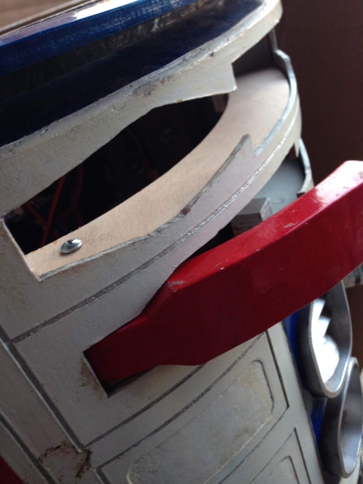
I say part, as the feet switch and cables are still inside R5's body, connected up. The switch goes in the hole next to the 'WARNING' label.

Next was to reinstall it back in place, wire up and test. The lead for the dome & the transmitter power were moved around. Power in was shown in the picture as channel 3, now in channel 6 socket - power. And the lead for the dome was moved to channel 4.

This is so that the left hand transmitter stick, auto centers after use.

Lightening R5's dome

Started this the beginning of the month:

With the new lazy susan planned, I started also looking at the frame work inside R5's dome.

With hindsight, this would/could of been made a bit lighter, but it was all new to me and since building the R0-D4 dome, I've learned a lot. There maybe some weight loss possible, removing edges etc, but the main weight is the actual top of his head. 18mm thick plus a WHOLE lot of car body filler for the cone angle top where the pie panels are.

Well, the 'Bad Motivator' electrics board could be made lighter, so started with that.
Here's a before and after, after doesn't have the aluminium bracket in the pic as probably won't be using it.
weight reduction
I used a thinner piece of wood board. The extra material was later removed as wasn't needed. Which reduced weight a little bit more.

R5's dome rotation upgrade 1.7 - metal ring

I needed to add some more pads & had Steve add some more tabs to help centralize the metal band. I was considering weight against thickness, but the thicker metal may have been a better choice in helping to reduce flex of the band. The additional pads and tabs should hopefully help with this. Found that these were not actually needed.

Next up was preparing the ring for painting. I'd already lightly sanded the ring and edges to key the surface and deburr the edges. I then used pin stripe tap to line edge & mask off for spraying up.

Using the original skin, I'd measured up about 25mm.

I then wrapped around the pin stripe tape and then masking tape.

~~~

Now Easter break is over, I was able to get back on with sorting out the new neck ring. It's not been easy, lol, with the dome in work sorting neck ring and clearance with the new bearing. Then taking the bearing and un-attached neck home, to check it all works on the body with the motor etc.

Well....... due to my unique skills, lol, the ring needed to be re-worked a bit. Then it was time to screw it all back onto R5's dome.

Glass fiber filler the gap between the metal ring and the wood. This was applied via the inside to also give some extra strength to the wood angled piece.

Wood filler applied:

This was then sanded smooth once dried. This side needed a bit more than the other.

Next up was primer. So I bagged up the dome and masking taped it off at the edge.
Using works spray booth makes life easier and breathable lol.
R5-D4

Due to time, I didn't take any pics of spraying up white, but it was the same as the grey pic lol. This work was done yesterday and left over night, to stink out works workshop.

This mornings little project was applying the neck's silver tape. Now, you can/could use silver spray paint, but this tape matches the other tape used on other parts of R5. Plus it re-matches the original he previously had.
R5D4
Goes on easy'ish, then used a cloth to smooth out all the edges & wrinkles. Next up was to trim off the excess.
Once I'd finished this, it was back into the spray booth to clear coat the new paint and silver tape.
Then once it was dry, it was de-bag time.
R5-D4
The white, is WHITE lol, so will need to be dirtied up a bit before Saturday's Lego Land event! It's amazing to see the colour difference over the time since I'd originally sprayed up R5's dome. Hopefully this should last him a few more years.

April 12, 2017

Utility Arm pivot points - upgrade time 2017

This wasn't on my list of 'things to do', but due to 'little fingers' lol, one of the utility arms, location pads had come loose. So over the last few weeks, this has been one of the other mini projects for R5.

Not bad considering the amount of action they've seen.
Link to post I blogged way back: Utility Arm Pivot pins fixing.

There's the loose pads.
Black mesh screen removed to gain access to rear of arms

Next was to remove the central support piece (the piece above the upper pad).
This was made of MDF.....yes, I hang my head in shame lol. But it was all I had at the time to support the center area.

I then measured up and cut out a piece of plywood which the new thicker pivot pads will be screwed to.
 The pad is temp screwed into place.

Again, just to show position of pad and pivot arm point pads.
This pad is a bit to short, so cut a new longer one.

I may possibly need to modify the servo arms if they are to be fixed to the new bracket. Tho the black mesh will also need to be modified, so if to able to, the servos can remain on it.
not pretty, but will do for now, until servo positions finalised
Drilled and screwed the pivot pads in place.


I also used the old center support to re-cut it out of 8mm thick plywood. The plan is to fit it to the arm pivot pads to make one unit. The 'center support' can be see mid section of the utility arm opening (screw head)

Work then on the upper arm. And as per usual, nothing is ever a simply 'copy/repeat' straight forward process. The pivot pads had to be modified more to:

a) fit
b) have enough material to be screwed into onto the rear pad.

(a normal build probably wouldn't have these kinds of problems lol)

This was achieved and so work could then continue on with primer & this time, matt black paint.

The above pic shows how the pivot pads were 'recessed' under the with of the arm. This was so there was enough material to screw into.
And here's the upper arm pivots attached to the frame pad along with the 'center support' for the arms and the outer skin.

Now these are installed and are a lot firmer, I may need to upgrade the servos to more powerful ones to be able to more the arms. This I'll be testing soon.

April 11, 2017

R5's dome rotation upgrade 1.6 - metal ring

My co-worker Steve, who's just a little bit handy with welding, said he'd be able to roll and weld up the new lower dome ring. So I drew up some sketches and talked through what would be needed. He then took the metal strip home over the weekend and got to cutting and welding.

this supplier has materials & options available to be cut to your own required sizes.

The cut material didn't need much deburring, only along one edge. This option is available on contacting the company. Steve welded on four 'tabs' that would be drilled and countersunk/t-nut's fitted to the wood part of the ring. The ring then screwed back in place onto the dome itself.

Welded ring with location tabs
This just shows the fit and tab position. The bearing isn't shown, hence the tab to wood gap.

Next was to mark and drill fixing holes in the tabs.


Next was to then press fit in the t-nuts and screw in the counter sunk bolts.

And of course, the test fit on the dome (held in place for photo)
The gap was needed as wanted to ensure correct fit, and wood being wood, it's not perfect lol. The gap fill be filled with fiberglass & resin, then smoothed off with filler.

This metal ring add's strength to the lower neck.

April 06, 2017

More Star Wars Celebration - You Tube kids TV

I tracked down presenter number two's video on You Tube, (back in February).


She doesn't get to talk with R5 (tho she was filmed doing so),
but he can be seen at the beginning of her 'mission'.

You Tube link to Disney Channel ES.

April 05, 2017

Star Wars Lego Land Weekend - April 2017

The UK R2 Builders Club will be attending

Star Wars Weekend at LegoLand Windsor.

We'll be joining forces with:


Myself & R5 are only able to attend on the Saturday, due to family commitments,
but am still really looking forward to this!

The weekend will be full of all your favorite characters!

Hope to see you all then.

April 04, 2017

R5's transport sledge 'upgrade work' pt4

With the new dome lazy susan bearing soon to be permanently fitted in place, the sledge will also need an upgrade.
In order for the lower part of the sledge to be able to lift up R5, the top struts (seen in the above picture) need to be trimmed to accommodate the extra 10mm or so of the new bearing. So I marked up and then jigsawed off the extra material. These have insulation foam on as can be seen in the lower right part of the picture, to protect him in transport.

Due to the position of the dome location bolts, the length of the struts needed to be shortened as well.
Bottom strut has a pencil line for where to cut to length. The upper strut in the above pic had already been cut to new shorter length. The foam was then re-attached to the struts as well as the cross beam strengthening piece.

R5's dome rotation upgrade 1.5

Had no free time the other weekend, so I had to wait till Monday back at work.

Due to more limited time, I was only able to work on clearance hole clearance & using my dremel, to grind down the washers that were overhanging the bearing inner diameter.

This is just to make sure that the dome motor wheel has a flat surface.

-----

This upgrade work involves a lot of multi-mini-projects lol. The electric upgrade, dome work, rotation/position of the lazy susan & next, the actual dome motor location and fixing.

I had thought about moving the motor to the front area of the body, so the wheel was at the top. But as I had already cut out an area, years ago in the build, for this position, I decided that here was just as good as anywhere else.

Next was how to mount it.....

I have a rear door stop on one of the vertical body struts, and it's in just the right position to mount the new motor spacer block. It will replace the original door stop at the same time. So I had to make up a new bracket for the motor/door stop, much more sturdier than the last bracket.
There was some thought in how to attach the bracket to the body frame, once the motor was attached to it, which prevented fixing it on afterwards.....lol, I don't make things easy for myself do I :D. The aluminium bracket fits to one side of the vertical internal frame, with a countersunk bolt and then a wing nut. This was the only way to secure, which was actually genius, as the wings stopped the nut from turning when the bolt was screwed into place!
Motor & bracket bolted into place.

Powered up the motor and the lazy susan ring spins great.


Update on the new lower dome metal ring to follow......