Showing posts with label wheels. Show all posts

July 18, 2024

Treadwell WED-15-77: transport sledge (part 2)

Wrote this the week before the Mshed event.....

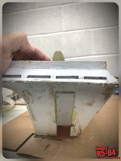
The bottom edge needed strengthening supports, so added two angular sides pieces.

The foam i had from work was cable tied on in place. A top one will also be fitted, more for protection when the whole unit is on the roof bars.

I needed to add some securing straps to keep WED on the sledge.

I added some wheels for easier movement and obviously a handle.

For protection and to look better lol, I needed to paint the sledge, so after a light sanding, primer coat, I finished it off with the same Blue paint I used for WED. I was going to go with Black, but changed my mind lol.
This is the only picture I have, from painting and at all lol. Must do better 😂

June 08, 2024

Treadwell WED-15-77: transport sledge (part 1)


So I’m going to need something for WED-15 to transported on safely. Not just at events but to them as well lol.

This is going to combine the two needs, hopefully, in one.

The idea is that the WED sits on the sledge and has restraints and wheels, this takes the strain off the tracks.


Then the sledge itself has location points so that it can be safely secured to my cars roof bars.


I picked up some straps, unfortunately not in blue lol.

The sledge also has padding planned on both ends to protect the base ends of WED and be painted as well…… TBD.

June 11, 2023

Treadwell WED-15 droid build : Part 18 - body/wheels


Month of June, and on my list of things to do for WED & things to source - parts:
  • Wheels : make/buy/3D print ?
  • Speed controller
  • Motors
  • Tracks : source & buy/make(?)/3D print ?
  • Receiver to use with the Flysky transmitter.
  • Batteries
  • Prime/fill/sand/repeat for the wood base.
Ordered some more primer paint this week.

I drew up a track from the plans in CAD. This was to add to the 3D build and possibly to 3D print in TPU. But the length is a problem for it to fit on the build plate lol, see picture 😂.

So for now it’s just for the 3D model.

Just to see what it looks like. I may have to make these…..how, I’m not sure….????

The rest of the week was working on the msin base:
  • Applied wood filler to certain areas.
  • Sanded once dried.
  • Primer arrived and so I continued on with spraying up the base.
  • Once dried I gave the unit a light sanding.
  • Then applied more light coats of wood filler to the areas that needed it, mostly to fill in the grain patterns.
  • Once this dried, I gave another light sanding. This repeated for some time lol.
Progress pictures:


Repeat until mostly happy 😃.

The same process was applied to the two lid panel hatches. The edges and wood grain were the focus of the work. The rear panel still needs a lower/inner skin of wood fitted.
Once the filling , sanding and primer painting was dry, I gave the whole base a coat of blue.


The two logic housing top panels that were the wrong size, I cut these down to fit under the mast base. These were primed and sprayed blue and clear coated. They were then screwed into place.

I decided to print off a drive wheel!
I had drawn it up in two half’s months ago, but rather than fit them together, I printed them off together as a one piece wheel. One thing I did add to the design was an angled edge on the inner edges. This is for helping align the inner track guide.

And here it is in a test fitting:

Before I left for the weekend, I set the printer to print off the other three drive wheels…… 2days 12hrs in total!!

The wheels have larger than needed axle holes, as this allows me some flexibility with the drive motors, shafts etc.

Drive setup:
Been looking at speed controllers & motors.
Just have to decide on 12v/24v and either belt/chain or direct drive of the main drive wheels.

May 29, 2023

R5-D4: Update April/May 2023

I’ve been giving R5 as he hadn’t been actually moved since Birmingham at the NEC.


New Dome motor wheel:
3D printed him a new wheel, as on the previous one the retainer nut wasn’t being held well and the PLA had been stretched. So I slightly modified some of the sizes and then printed it in ABS. Fitted the nut and 'o’ring and then fitted it onto the motor shaft.

Test was on Saturday at…..
 ...April

Next up was to connect up the new receiver. This didn’t take me to long, compared to the nightmare I had trying to sort it out when at Celebration 🙄.

I didn’t need to connect power (previous TX require power), this one utilities the power from being connected by the servo leads. Jacking up the wheels meant I was able to setup the drive and steering channels, plus the extra switch ones, for the utility arm, sounds and (once I have the long enough servo lead) I’ll be able to trigger the trading card dispenser.

Trading card dispenser:
A while back, I made a new trigger control box that utilised a servo controlled relay, instead of the previous remote control. Once the servo lead arrived, I crimped on new plugs to connect up the TCD control box.

View Blog post here.

But on testing it….. I realised that it needed to have a momentary activation rather than an actual ‘switch’. So I’ve been on Radio Model Workshops website and will be ordering a single RC switch relay, which has the option of it being a momentary one. So this control box will get another upgrade when it arrives.

In the meantime, I swapped the control box back over to the remote control version and 3D printed a new box for the remote, so that it could be attached to the new rear panel I’d printed off for the new Flysky transmitter.

I drew up a button bracket, that fits into one of the rear screw hole sockets, this will be upgraded again to look better and also hold the LED in place.

May 9th

Outer foot ankle lock:
The outer foot shell needed some repair to it, so with the legs off the body, I stripped the outer foot down. The ankle locks unbolted and the ankle bolt nut (previously held in place with super glue), fell out lol. I knew I needed a better way to hold them in place. I had thought about a lock washer, but then a lightbulb 💡 moment came. I measured up and drew up a nut holder to 3D print. It would be held in place by a bolt.
Nut holder loose.

Nut holder moved into position. I applied some thread lock to help keep it in position, but only nipped it tight to allow the ankle bolt to locate through into the thread.

I’ve added the file to my Prusa page.

The wooden foot shell got cleaned up inside to allow the new glass fibre to bond properly. Good as new again.


December 09, 2022

Treadwell WED-15 droid build : Part 6 - 3D printing neck / neck bearing


November/December
This post has been delayed due to being home resting and not being able to do any work or 3D printing.

The neck bearing (£6.99) arrived Nov 29th
The aluminium plate arrived Dec 6th
The claw, not arrived yet……

Purchased PVC tube from: Wickes £4.00

The upper mast/neck required an upgrade to it’s design to reduce the gap between it and the head base plate, so that the bearings were located better and the gap present was reduced.
Spacer ring and bearing location ring.


These two are glued together and then glued into above picture location.

The bearing race and its washers, locate in the ring recess and the motor shaft connects to the mast attachment (which is secured to the base plate.

This has now been achieved and am much happier with the look.

Mast Base Connection:
I thought about the Mast’s base connection to ensure that it is supported. The idea is to use a piece of Aluminium, as a strong flange component, to secure the mast to the upper section of the wheeled base.

Wheel Base:
I have gone through my stash of wood sheets to work out what I have to make a start on the wheel base.

Wheel axle bearings. Scooter bearings held in place with 3D printed holders??
Have been researching what’s available.

Wheels:
I draw up and will 3D print a test wheel, depends on how this turns out, strength wise, being able to support the weight of everything.
I may turn them out of aluminium or Nylon, for the middle ones.

Mast construction:
With working/printing on another project, the weekend was free time to print off six (6) pieces for the mast. Total time, about a day+.

June 19, 2022

Reinventing the wheel……

😄😄😄 lol, yes…..aaaaaand no.

Back in April (last month)….
R5’s ride height has always been an annoyance for me over the years. Most noticeably at events on nice flat surfaces where I can clearly see the wheels. [for film appearance's 😎, this isn't so much of an issue]

Also the feet internals weigh quite a bit and they don’t support the floating foot shells very well.

So, I decided I needed to redo them to be lighter and lower.

Using my original internal feet frames, I drew the new versions up in AutoCAD inventor and then 3D printed out these test pieces.
This build structure is not new, but as buying the components might not fit my 'UNIQUE' foot shells, designing my own to fit made sense.
Above is first draft printed. The cut outs were just to save filament.

Test fit inside the foot shell.

And showing the reduced protrusion from the bottom of the shell.

I’ve ordered some aluminium plate, for the frames off eBay.

The first sheet of metal arrived.

Nice……👍🏽

Due to a family event, the funeral of my Grandmother who reaches 105years, the project was paused.

May 2022
Tuesday 3rd: was cutting aluminium plate day. I got out a hacksaw and started cutting out the main side plates.
I was also figuring out bolts, spacers and nuts.

Additional plates are on order, the two hashed areas on the 3D prints [above picture] are not needed so will be removed.

Found some suitable Stainless Steel tube, which will be great as the spacers.
I’ll be using M6 bolts and Nylock locking nuts, which I bought from local DIY store.

The steel tubing needed to be squared off at the ends, so used the lathe.
The bolts have washers both ends and locking nuts.
I drew up a shell support to help keep it from tipping over, as the shell 'floats' on the inner frame. This I 3D printed off to save weight. It's held in place by the longer bolts, washers, nuts.

Next up was creating retaining clips for the aluminium channel strip. First idea was hollow, but thought, it doesn’t have to be. So cut it in half and turned it into a clip, that snaps over the spacer tubing.

With the new frame layout, it will also be easier for me to access the ankle bolts, nut. On the original steel frame, I had the nut welded in place. Now, I’ve got nylock flanged nuts.

Next was to drill location holes for the front caster mounting, angle plates. And I positioned the caster to be more inline with the rear wheel.


And here’s the completed assembly, with motor and caster fitted. This whole assembly is so much lighter than the old one.

I have already made a start on cutting out the second set of plates. So this will come in a following post.

June 2022
Back in work after a short break away and back on with cutting out plates for foot no2.

….a rushed week of getting everything sorted before attending Saturday 18th’s event at Stars of Time, in Swindon’s steam museum. But got everything installed Friday night lol.

Event report to follow…..

January 25, 2020

Another mini project 1.9 - Trading Card Dispenser

Yesterday I uploaded the stl files and the assembly instructions to the UK builders club forum.
The components take a while to arrive so it will be a few weeks before I get any feedback. But as I’ve printed the same version, there shouldn’t be any problems lol.

The other fun part was creating instructions for 3D printing (orientation & support placement), assembly of the bought components and then fully assembling of the unit itself.
Created a PDF to be downloadable with simple instructions.

I finished printing my frame holder to fit into R5 so hoping to get this all installed and tested soon. There’s still work to be done with alignment etc, so more posts on this to come.

January 23, 2020

Another mini project 1.8 - 'Trading Card Dispenser'

So after a bit more fine tuning,
the TCD is now complete.


The TCD..... The 'Trading Card Dispenser'

I was still waiting for an electronic component to arrive in order to wire everything up to test it. It arrived and it wasn't what I was hoping for, so I'll have to revert back to my original electronics setup, not a big deal as this doesn't effect the actual dispenser being assembled or operated.

I've designed this as a self contained unit with it's own remote controller & timer delay off circuit, but it would also be able to be controlled via any momentary switch, Arduino etc. I'm not an Arduino guy, but from what I know this is possible.
The motor runs on 6v and would only need to run for a few seconds.

The unit comes in 4 parts, base (in red), plate (in blue), lid (in green) & a wheel adapter which fits onto the motor. (colour's are for identification only, not actual)

There are then 4 components required to be bought in order to fit and glue together to fully assemble. I'll post up this list and an assembly instruction PDF when files are released.

More updates soon.......

December 18, 2019

Another Mini project 1.4 - ‘Trading Card Dispenser’ - micro motor

Been working on some more redesign’s for this project. Been working, learning how to creating catches, the mini magnets didn’t have enough force to work effectively.

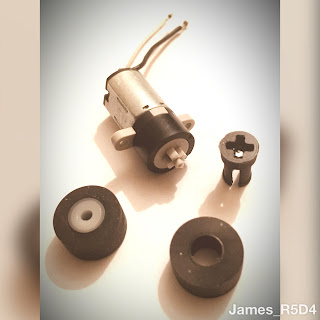
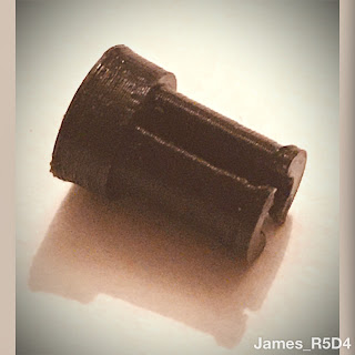
Did draw up a new ‘axle’ for a rubber wheel, which comes off a tape deck (available off eBay). Only took two attempts to get the part to fit on the mini micro motor lol.
gear motor, 3D printing

3D printing,

This worked great so it's on to the next idea was adding an extension to this to add a second rubber wheel.
And here's the components in 3D view.
gear motor, 3D printing
The green part is the axle extension.

July 11, 2017

R5's transport sledge 'upgrade work' pt5

The small caster wheels on the skid where not up to the job and became a pain whilst loading into rear of car. But they needed to be small to keep the sledge at a height to fit in the rear of the car, so I'm not mad at them :D.

I looked at collapsible sack truck's but reports I've read recon that unless your droid is light, then they can't handle the weight. And I'm not up for spending loads of money on a solid fixed one. Plus the fact of then having to load for transport to events with already limited space, were also negative points.

I read on www.astromech.net that one builder had done a similar thing to my way of thinking. But instead of lifting brackets, he's used large threaded hand wheels. But how R5 is, foot heavy, I didn't want to be struggling holding the overhang of the sledge up with one hand, whilst trying to unscrew the locking hand wheels.

So my idea was to build a removable set of wheels, but sack truck style.
I cut up a piece of 18mm thick Plywood, attached two old, large, rubber'ish wheels and made up two brackets that hook underneath the transport sledge. The brackets were something I had keep from something that would of needed fixing brackets lol. Always good to keep stuff. One of the brackets I bent and is a little bit snug fitting on the bent edge, but it goes on and stays put, so not the end of the world.

The wheel brackets have T-nuts on the rear face, countersunk. I only had hex bolts the right length, two of which needed to be cut to a more suitable length.

Tried it out last night and it didn't break :D
 Wheels fitted, next was to mark out the bracket position.


 Countersunk T-nuts, as this is the face that will be up against the sledge.

And here it is test fitted, before I then gave it a mini test run, lol.

The metal brackets are very strong, and should last.
But if they don't I can fabricate some new ones.

Next up is to fit some sliding strips to the rear of the sledge.
Less resistance, point contact etc.

April 04, 2017

R5's dome rotation upgrade 1.5

Had no free time the other weekend, so I had to wait till Monday back at work.

Due to more limited time, I was only able to work on clearance hole clearance & using my dremel, to grind down the washers that were overhanging the bearing inner diameter.

This is just to make sure that the dome motor wheel has a flat surface.

-----

This upgrade work involves a lot of multi-mini-projects lol. The electric upgrade, dome work, rotation/position of the lazy susan & next, the actual dome motor location and fixing.

I had thought about moving the motor to the front area of the body, so the wheel was at the top. But as I had already cut out an area, years ago in the build, for this position, I decided that here was just as good as anywhere else.

Next was how to mount it.....

I have a rear door stop on one of the vertical body struts, and it's in just the right position to mount the new motor spacer block. It will replace the original door stop at the same time. So I had to make up a new bracket for the motor/door stop, much more sturdier than the last bracket.
There was some thought in how to attach the bracket to the body frame, once the motor was attached to it, which prevented fixing it on afterwards.....lol, I don't make things easy for myself do I :D. The aluminium bracket fits to one side of the vertical internal frame, with a countersunk bolt and then a wing nut. This was the only way to secure, which was actually genius, as the wings stopped the nut from turning when the bolt was screwed into place!
Motor & bracket bolted into place.

Powered up the motor and the lazy susan ring spins great.


Update on the new lower dome metal ring to follow......