July 27, 2012

Large Data Port - 1.5 - More Blue paint

Have now sprayed up the side parts of the Large Data Port, with Blue paint.
These will be glued in place later on in the build, once the skin has been sprayed up white.

Utility Arms 1.3 - Pivot Pins & RED paint


Cut a length of 8mm dia dowel to use as the pivot for the Utility Arm. Then when in work, I found some scrap Aluminium bar the same size, so used some of that. I drilled through the arm with an 8mm dia bit. I then clamped up the piece of Aluminium in a lathe and used emery cloth to smooth over the diameter.

This is now a snug fit, but not to tight once it was push fitted into the arm.

Cut two blocks out of M.D.F. to be the top and bottom dowel location holders & drilled 8mm dia holes in them. Then I cut them across the hole line. So to clamp the pivot pins. I cut clamp block, but the wood broke when the screw was fitted. M.D.F. section also started to split :( so made a block to hold the clamp block to the frame uprights (proper wood lol), then realised, OVERKILL!!!
So just screwed the 1st clamp block into place, using a clearance hole in the top ring.


How I'm going to do the lower arm retainers ??


This idea is again, me following in the footsteps of others:
Victor's R2D2 Build diary (2009).

Stripped the bits and applied more primer.


Sanded the arm again then sprayed it up again, to check finish.
Changed from the screw to a nut and bolt for the clamp block. Removed the lower section to drill the hole and then sprayed both sides with primer.


As all the 'visible' parts will need to be painted.
Then a coat of white on the Utility arm,


then next, will be some nice Red paint!
Just need to add a few clear coats :)

July 23, 2012

Body Skin 3.8 - Utility Arm socket 1

Made up a paper template from the Utility Arm and transfered it onto the Body Skin. I marked a clearance area around it and roughly cut this out, using my Dremel. I used the sanding drum on the Dremel to get down to the line and used a small file to square off the edges. I then applied PVA glue (watered down) to seal the edges.

Next, I'm going to finish off the Utility arm and then sort out fitting it in the socket.

Utility Arms 1.2 - The Claw

Used the sanding unit's in work today and smoooothed off the wood filler. Next I marked up and cut out the 'claw' part of the arm. It's not to 'club specs', but close enough for me and the wood's strength lol. Then applied some more wood filler, where needed, so they look messy again in the pictures :D

July 21, 2012

Utility Arms 1.1 - Arm less

Marked and then cut out the second piece. Vice clamped then I drilled, counter sunk two holes, then screwed the two pieces together. Next I marked the angles on and cut them out.
I'm sort of happy how this one has turned out, still needs a lot of work so am positive it will look ok when finished. The areas marked with red marker, are where I need to work on next. Trimming edges and major application of wood filler :D lol.

July 20, 2012

Utility arms 1.0 - the build begins

Utility arm part one of two parts that will be needed for both sets of arms. I'm coping a build that was originally done here http://podpadstudior9.blogspot.co.uk/ .

July 19, 2012

Coin Slot up-grade 1.2

Started on drilling holes in the back's of the coin slots to accept 4BA screws (smallest suitable thread I could find). These will go through the perforated metal angle [with clearance holes in] and then be screwed to the inside frame upright.
 Positions marked onto the angle.
Coin Slots all drilled and thread tapped.
Just need to cut down in length, the four on the left of picture


This is them starting to be assembled


A few of the clearance bolt holes were off centre, so had to file them up for the screws to fit.


I like the fact you can see the perforated metal through the slots :)

July 16, 2012

Body Skin 3.7 - Rear Hatch **COMPLETE** & some more front panel grooving

Sanded the wood filler filling the gaps between the skin and second coin return. Then used small paint brush to 'touch-up' the filler. Next was to touch up the red panels around the edges. I added black paint ot the grooves and oter places as 'oil/dirt' marks.
The whole rear hatch was then sprayed with clear sealer & once dried, the Power Coulper was fitted and secured in place with it's bolt.
Grooved out and recessed the panel which will have the Restraining Bolt fitted to it. Also the Front Vent surround groove and also the Utility arms grooved surround.
Then sealed it with watered down PVA glue.


Before I finished up for the night, I bent some perforated metal that was just the right size.
This will be used for fixing the Coin Slots [front view] to it from behind & fixing to the frame.

July 13, 2012

Large Data Port - 1.4 - Blue sprayed

Wood filler, sanding and then primer sprayed up the parts for the Large Data Port.

Then once dried, sprayed the upper piece blue metallic. Followed by clear sealer.


And lower piece

Then test fitted into place in the frame
Not 100% accurate at the moment, but working on fixing this.
Large Data Port screwed into place

July 11, 2012

Large Data Port - 1.3

I've decided on NOT fitting the perforated metal behind the L.D..P opening.

Tapped in some panel pins, parallel to each other. Then drilled larger clearance holes in the front of the top ring. These will help to tie in the top piece of the L.D.P., for when the P40 resin is applied along the inside edge.
The pencil lines are where the panel pins are, you can just make them out.
Applied wood filler also to the leading edge angle, last night. Then lunchtime today I used the works sander to sand the angle flat and smooth.

I primer sprayed up the lower piece. Then marked up and cut out two side pieces.

July 10, 2012

Large Data Port - 1.2

So I've now cut out the top piece, shaped it to fit and used the sanding machines in work to get red of the edges. Next I need to add the front lip angle. I Positioned the lower lip piece into the frame and drilled some holes through the top ring. The lower piece will be screwed from the underside.
Upper section, marked ready for addition of angled edge [front line] and cutting to size [rear line]
Test fit of upper & lower sections
Wood filler applied to areas needed

July 09, 2012

Large Data Port - 1.1

I already had a piece of MDF cut out that was going ot be the top section for the top Utility Arm location. This fitted nicely and will probably be screwed to the top ring. Am thinking I won't be cutting the ring thickness down [underside, up] so that you could see through the L.D.P into R5. Will probably go with the perforated metal, sprayed black.

So I marked the angle to be cut on the MDF piece, which I'll be calling the lower lip piece. Then using my mini saw, I stared hacking away lol.


L.D.P. Large Data Port
Lower angle for Large Data Port [L.D.P.]
I sanded it a bit smoother, before applying watered down PVA glue.
This hopefully should harden the exposed MDF up a bit.
I'll smooth over with wood filler in places that need it later on.

I also measured and marked up the top piece of the L.D.P.
To be cut out of 8mm thick plywood.

July 07, 2012

Large Data Port - 1.0

I wasn't sure how best to make this. Loads of people have made their own L.D.P's (Large Data Port's), but their frames already had the cut-out. I was going to do this bit later, but now I don't really want ot remove the skin, so...... Could I build the lip up using P40 resin or would I need to cut into the top ring like it should be!?!?!

Well I went for the latter and started cutting wood.


R2D2, L.D.P., Large Data Port
Over half an hour later, job (almost) done....

Body Skin 3.6 - Rear Hatch 2nd Coin Return in place

I bonded on the second rear Coin Return, using P40 resin.
And then once dried, filled the remaining gaps with wood filler.
coin return on right, bonded in place
wood filler in gaps

Once dried and sanded, I'll paint the filler with silver paint to blend in.

July 04, 2012

R5-D4's Motivator 1.3

For part 1.2, which was only spraying up silver, go to this post

I used Humbrol black tinned paint and using a brush, did a process called dry brushing, over the parts of the Motivator. This helps to pick out the high point details and also dulls down the  silver paint, hopefully to give it a charred/burned look.

I cut a piece of coated wire and then fed it through two holes, one near the top and the other into the side of the 'stump'. These were then glued in place. Next I drilled a hole through the 'heat sink' (again, for want of a better word) into the 'stump'. This was then pinned and glued in place.  I then added some extra electronic components I'd saved and glued these in place.
The mesh is not fixed in place yet, I need to sort out internals for fixing to the Dome and also to stop little fingers from pushing it deeper inside lol
I then went and re-painted with more black paint, made it really dirty :)

July 02, 2012

Body Skin 3.5 Body work, all over

The other day I started cutting out the slot's in the side vent.
You can just see them on the right of the picture.
Next I marked up and cut out some more perforated metal sheet,
that will be used behind these side vents as these are very weak by themselves.

SHOULDER HOLES

I applied watered down PVA glue to the cut hole edges, then used some more P40 resin in the gap around the shoulder disc (shoulder disc has been removed in these pictures). Then later I started to add wood filer.
Used the left over resin by applying it to the back of the vent 'pocket' back.

Whilst all that was drying off, I cut out the second hole for the shoulder disc.
No mistakes this time!!
I cut well inside the line, then repeatedly offered up the disc, locating it on the bolts, till it fitted and the clearance around it looked right.
Other work done:
I sanded the wood filler on the recessed panels again.
Primed and blue sprayed up the second pocket vent backing plate (this one will go on the rear of the body). 

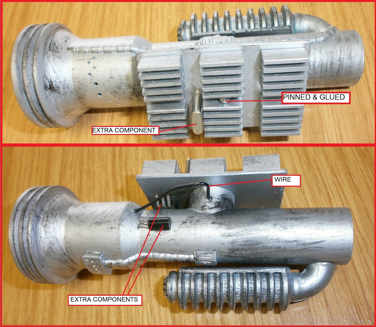
R5D4'S BAD MOTIVATOR

Bought a new silver spray can so sprayd up the second rear Coin Return & the components that make up the Motivator.
Motivator bits [top of picture], rear Coin Return No2 [bottom of picture]

PANEL WORK

Lastly, I had time to recess the panel next to where the Coin Slots go.
 
The left picture shows the panel scored ready to be carved out. the right pictue shows job done, and with watered down PVA glue applied, to seal. This also helps to stop the wood soaking up the spray paint :)
Yellow shows work done