

Part 4:
Last week was a busy one designing components and how best to make everything fit together lol.
I 3D printed the central eye rod, which will connect to the servo horn extension piece (I had already drawn up the servo horn to be used on R5’s Bad Motivator setup). This may be swapped over with a metal servo horn later.
Here’s latest assembly showing the central rod and servo horn extension piece.

Next was a tie bar to keep the eyes connected and moving together and printed it off. Not sure if I’ll be happy with this idea yet. The central rod servo assembly is shown just in mid position for the picture above.
Here’s link to YouTube short of manual test movement.
Looking at a heavy duty servo, just in case a standard one isn’t up to the task.
I made a start on the ‘mast’ part of the droid, using this image:
Also, this version that was built by:
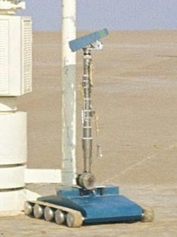
Paul6700

I sectioned up the mast, so that the components can be printed separately.
The plan is to use 40mm dia PVC tube, that the 3D parts fit over. All glued and screwed together. I had planned to print the mast parts over the weekend, but have held off for the moment.
Here’s an assembled picture anyway.

After a comment on my Build Blog over on www.rebeldroids.net , I decided to pause and rethink the mast to base plate union…. It got me thinking about the fact the mast rises up (deleted scene), so I’m redesigning this piece.
I have a motor that used to fit on R5 somewhere. This will require the upper mast to be redesigned to accommodate it.
Before the above pause came into effect, I’d already printed off a ‘cap’ for the mast that fits inside the mast/base plate hole.

The original idea (which still may happen) uses PVC tube which will fit up inside the upper neck piece. I also printed a template so that the tube could have slots cut into it at the end, to locate it into the ‘cap’.
See picture below showing the inside of the cap. The template will help cutting the tube to match.

Here you can see the three screws (bolt’s) in the extension parts of the cap.
Well, progress is paused for now until I redesign the rotation setup.
**********
Don’t forget this coming Sunday….

Weston-Super-mare
No comments:
Post a Comment