This page is to document how I built my wood R4 type dome.
All the step by step's can be found on my Blog,
just go to the search bar (if using the web version) and look for R4-D4
After building R5's dome, I wanted to build an R4 type dome, but this seemed a daunting project. Then 'The Last Jedi' came out and the talented Lee Towersey & Oliver Steeples, showed us a new type of dome, the R0. This was similar to the R5 I had built, so I decided that this would be my next (second) dome project.
With the experiance of building these two domes, I was more knowledgeable about how to work the wood into the R4 shape that I wanted it. And so I started on building an R4 dome.
September 2017.
I had drawn up in CAD using dimensions available on www.astromech.net how I was going to build this dome and how to attach the pieces together to form a strong structure.
The centre dowel in the above pictures, was just for testing,
to give support to the top hexagonal piece.
One thing I already know was that this dome was going to be light weight.
The wood used would give strength and support, without overly adding to the weight of the dome, where possible.
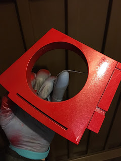
Here the upper hexagonal section has had it's centre removed. To save on weight, but also as I learnt from my R0-D4 dome that having easy access to the inside via a lid was a really helpful thing to have.
Here I started making up the holo pod for the holoprojector to fit into, as can be seen in the above picture. I wanted to test my ideas for constructing the holo pod. Here I carved a slot into the sides and top to secure the holo pods face plate.
The holoprojector is 3D printed. The stl files were the ones used on the astromech forum. There are versions available on Thingivers and other sites as well.
But these are versions created from the actual drawings for the original air vent's used from salvaged planes.
On with the build.... I fitted two of the triangle pieces onto the frame work. Next was to make a start on the curved panels.
I made a cardboard template and transfered this onto the hardboard.
The shape of these pieces is a large radius at the bottom, but a tight radius at the top.
I scored down the curved panel so that I could bend it round into shape.
This was not easy and once I was happy with the edges fitting between the two triangles, I glued and pinned the panel into place.
Once this was glued and dried, I used a rasp file to shape the flat/high spot outter surfaces into a curve. Then I applied watered down PVA glue. This helps to strengthen the wood by soaking into it and bonding the fibers together. This is especially helpful for later with the spray painting, as it prevents the paint from being absorbed. Once the wood had dried, I started to apply wood filler to the slots and gaps in the curved panel.
This process was repeated for all the curved panel
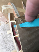
The ends were trimmed, and the edges blended into the adjacent traingles
and all smoothed over with wood filler.
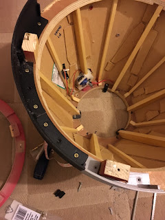
Here's an internal picture of the domes structure.
In the above picture, you can see I used off-cuts to help strengthen and bond the curved section join edges to the triangle panel edges.
As this was a work in progress for this curved panel idea. I worked around the dome in sections. Sanding the curved panels, applying wood filler, sanding and shaping. Then I would apply filler primer, this helps fill up gaps and after a few coats, plus sanding, really helps with the shaping of the panels.
Below is the top lid. You can see the yellow paper used to mask off three of the panels.
Along with the red masking.
Ready to be re-sprayed white on the already sprayed red work.
The 'eye' part of the radar eye, was again created using a 'fake CCTV' camera's dome.
These can be found on eBay, though my original one I used for R0-D4 I found in a pound shop, so search around if your able to.
The dome part of the CCTV was taken off and placed behind the radar eye.
Then marked roughly and the dome part needed was cut off with a saw.
This was then sprayed matt black on the inside, so the paint doesn't scratch off and then was glued in place from behind.
Last parts that were worked on where the holorojector ring.
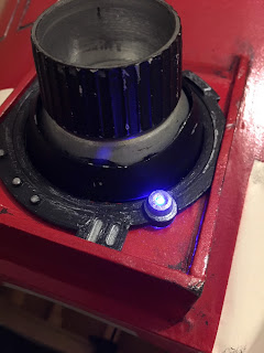
I needed something to cover over the holoprojector location screws, but still be able to access them if needed. So I drew up this ring that could be glued/hot glued into place.
[This is a 'non standard' item]
I then painted it up wired in the electrics.
Blinking LED.
I did start work on automating the holoprojector. These attempts are documented on my Blog, but after a few attempts and fails, I decided to put this on hold for a future try.
And this is the dome fitted onto R5's body.
I took this picture at MCM Comic Con in Birmingham earlier this year 2019.
As the dome stands out, there's no need to modify the body colour scheme from R5's original colour spec.
I hope this page was of & is of use to anyone attempting to also build an R4 dome, or just helpful in giving you ideas about creating your own work.
Thanks for reading.
September 2017.
I had drawn up in CAD using dimensions available on www.astromech.net how I was going to build this dome and how to attach the pieces together to form a strong structure.
The centre dowel in the above pictures, was just for testing,
to give support to the top hexagonal piece.
One thing I already know was that this dome was going to be light weight.
The wood used would give strength and support, without overly adding to the weight of the dome, where possible.
Here the upper hexagonal section has had it's centre removed. To save on weight, but also as I learnt from my R0-D4 dome that having easy access to the inside via a lid was a really helpful thing to have.
Here I started making up the holo pod for the holoprojector to fit into, as can be seen in the above picture. I wanted to test my ideas for constructing the holo pod. Here I carved a slot into the sides and top to secure the holo pods face plate.
The holoprojector is 3D printed. The stl files were the ones used on the astromech forum. There are versions available on Thingivers and other sites as well.
But these are versions created from the actual drawings for the original air vent's used from salvaged planes.
On with the build.... I fitted two of the triangle pieces onto the frame work. Next was to make a start on the curved panels.
I made a cardboard template and transfered this onto the hardboard.
The shape of these pieces is a large radius at the bottom, but a tight radius at the top.
I scored down the curved panel so that I could bend it round into shape.
This was not easy and once I was happy with the edges fitting between the two triangles, I glued and pinned the panel into place.
Once this was glued and dried, I used a rasp file to shape the flat/high spot outter surfaces into a curve. Then I applied watered down PVA glue. This helps to strengthen the wood by soaking into it and bonding the fibers together. This is especially helpful for later with the spray painting, as it prevents the paint from being absorbed. Once the wood had dried, I started to apply wood filler to the slots and gaps in the curved panel.
This process was repeated for all the curved panel

The ends were trimmed, and the edges blended into the adjacent traingles
and all smoothed over with wood filler.
In the above picture, you can see I used off-cuts to help strengthen and bond the curved section join edges to the triangle panel edges.
As this was a work in progress for this curved panel idea. I worked around the dome in sections. Sanding the curved panels, applying wood filler, sanding and shaping. Then I would apply filler primer, this helps fill up gaps and after a few coats, plus sanding, really helps with the shaping of the panels.
The above picture shows the edge of a curved panel being clamped whilst the glue sets. The panels to the left have had filler primer applied and more wood filler applied after sanding smooth. The holo pod can also be seen.
These two show more of the process of smoothing, applying more wood filler and also test fitting the position of the radar eye (which is a 3D printed version) kindly donated by Paul F.
~~~~~~~~~~~~~~
HOLOPROJECTOR
Whilst all the above was going on, I was also printing off in 3D a holoprojector.
Printed, sanded and then primered.
These files I got off the Astromech forum, tho later on I drew up my own holoprojector & rear cowel, as I wanted to use a light/servo control board which fit's inside. More on this below.
Before I moved onto my own holo design, I started on a mini project to illuminate the projector, but to over come the dredded 'cable twist' that happens when kids & adults grab hold of the holoprojector and rotate it around and around.
There are a few ideas/solutions out there, but no one had come up with this idea.
I used a bearing! the LED unit fit's through it and similar to a slip-ring, the unit can twist without tangeling the wire.
This first idea to test the principle, worked, but required more space for the wires.
So next iea was to use a single large LED.
The LED sits in a cup, it's wires pass through the middle of the shaft.
The shaft push fits through the bearing, with the wires coming out behind it.
The barbed sleeve fits inside the holoprojector.
Once I was happy with this, I went on to paint the units up.
Next up is I wanted to add weathering to the ribbed front of the projector.
So I applied more masking tape and then rubbed off the edges.
Then I painted over the cut masking tape, which had exposed the black nozzel.
And here's the holo, light up test, with the LED
I later redesigned the holoprojector main body to be able to accept the REON board, but I had a mishap which burn't it out. I've not got any further with that idea.
~~~~~~~~~~~~~~
Back to the dome....or actually, the lid.
This was the next thing to make and was as simple as it being just a flat board, cut to size.
The edges were then shapped to size and to give a rounded edge so as to look more natural. Here it is primered and with location tabs fitted.
I created two 3D printed sockets to accept the tabs (seen in above picture) I also 3D printed up a magnet holder to help lock the lid in place.
I glued a washer onto the underside of the lid.
The next challange was to add all the grooves.
This I knew how to do as it's the same process I've used on R5-D4's main body.
Firstly I drew onto the dome all the panels and their groove edges.
I then scored with a stanley knife, a few millimeters deep into the wood. Remember that the wood had already been washed over with watered down PVA glue.
(The glue is absorbed into the wood fibres sealing and hardening it)
I then used my grooving tool, which is actually a machining tip tool used on CNC machines for creating grooves & undercuts in metal. See picture below....
Once I had finished the lids grooves, I applied another PVA wash over the exposed wood to strengthen & seal it.
This process of grooving was carried out for all the panels on the dome.
It's a very time consuming process.
I was also working on the correct height needed for the lower dome ring.
This is the piece that fits onto the body's bearing race.
This as to be expected, is not as straight forward as it might seem.....
it usually never is with my builds lol
These raised pieces had to be added, before I made up the curved panels, as they had to be screwed in from above, for strength.
I later found that I had made these too long so had to cut them down on length.
Then came the lower ring which fits onto the bearing.
The red circles show the location blocks added to the lower ring. These were drilled first to fit over the location bots already fitteed into the bearing. They were marked and screwed into the wood part of the ring.
My original idea, as with the R0-D4 dome & R5's upgraded dome work,
was to have a metal neck ring.
Unfortunatly this wasn't able to happen due to my firends roller machine not being able to accomadate the width of the metal strip......this only became apparent much later on in the build, so I had to change this idea and came up with 3D printing the neck ring in sections.
These were going to be clipped together with 3D printed clips, but decided to 'weld' them together using a soldering iron.
The next stage, which was the spraying of the dome. As you can see in the above pictures, the dome had already been sprayed up, but the 3D printed neck had to be sprayed up later.
White top coat applied to the dome and lid.
A few coats applied and allowed to fully dry.
Next up: work out what area to mask off that wasn't going to be sprayed red.
I had a few ideas and used film/toy ref pictures so that the design was familiar, yet not a direct copy of exsisting droid colour schemes.
Due to the neck ring being added & a missed creating a pair of grooved panels.
I had to re-spray the dome, with red & white lol.
Along with the red masking.
Ready to be re-sprayed white on the already sprayed red work.
And then re-re-sprayed with red again.
Here's the neck ring, primered and prepped ready for silver spray.
The white undercoat needed to be covered with red, but this wasn't a simple job as the colour didn't match. So I had to re-re-remask off the dome, not all the panels though. This turned out great as now they didn't match the red dome.
As can be seen in the picture below.
~~~~~~~~~~~
The R4's have some nice 'fake electronic' exposed panels at the top of the dome.
I had already 3D drawn up and printed off some little bits, these were then all combined into one piece, to create my own 'fake electronics' panel.
These are available on my Thingivers page (click for link)
Next up was cutting out the panels in the domw to accept these fake panels.
Two off, one per opposed side.
As you can see, this work shows that the dome has been painted.
The reason is I've skipped a stage. I first only recessed the wood, just noticable in the first picture. I wasn't happy with this look, and I decided on the above alteration, after I had sprayed up the dome.
Here is the fake elctronics panel sprayed silver & fitted.
As you can see in the abve pictures, the fake panel is now recessed and doesn't protrude above the surface of the dome.
.......much happier.
~~~~~~~~~~~~~~
The 3D printed radar eye, was kindly given to me by my local friend Paul.
After some sanding, filler primer, more sanding. It was then sprayed up red to match the dome.
Once dried, I painted on the silver groove detailing and also added some weathering to give the chipped paint effect.
The 'eye' part of the radar eye, was again created using a 'fake CCTV' camera's dome.
These can be found on eBay, though my original one I used for R0-D4 I found in a pound shop, so search around if your able to.
The dome part of the CCTV was taken off and placed behind the radar eye.
Then marked roughly and the dome part needed was cut off with a saw.
This was then sprayed matt black on the inside, so the paint doesn't scratch off and then was glued in place from behind.
Last parts that were worked on where the holorojector ring.
I needed something to cover over the holoprojector location screws, but still be able to access them if needed. So I drew up this ring that could be glued/hot glued into place.
[This is a 'non standard' item]
I then painted it up wired in the electrics.
Blinking LED.
I did start work on automating the holoprojector. These attempts are documented on my Blog, but after a few attempts and fails, I decided to put this on hold for a future try.
And this is the dome fitted onto R5's body.
I took this picture at MCM Comic Con in Birmingham earlier this year 2019.
As the dome stands out, there's no need to modify the body colour scheme from R5's original colour spec.
I hope this page was of & is of use to anyone attempting to also build an R4 dome, or just helpful in giving you ideas about creating your own work.
Thanks for reading.
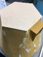
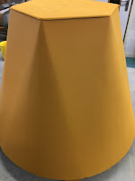
Blog update: lid modification:









can i ask would it be possible for you to list all the materials used in this dome build please as im wanting to do something very similar to this or even if you could email a list of the materials please much appreciated
ReplyDeleteI’ve added a new Blog link to modified lid.
ReplyDelete