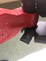
So after looking at how other’s had done this, I started looking at how I could design something up for my wood arms. AutoCAD inventor fired up, I started drawing up a bracket, that I can somehow fit/fix to the arm.
This is first design, but only had time to print one idea off. Got home and after test fitting, above pictures, I realised that the better fit would be flipped upside down, so that the arm part of the bracket face the other way. This would then clear the arms angle edge.
So a new design on Monday will be drawn up, also with some other ideas as well.
Version 2 print needed some more alterations.
Version 3 print needed some additional redesigning to include more support & possible fixing points.
Next up was looking at how to protect the servos from being over stretched. R2 builders who have opening pie panels on their domes and doors on their bodies, use this idea of spring loading the link rods. This gives some play as the springs take the additional strain of the panels being manually opened at events & damaging the servos.
Here the linkage protection is being tested on the first utility arm bracket.
More updates soon.


No comments:
Post a Comment