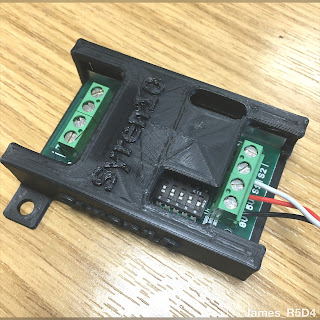
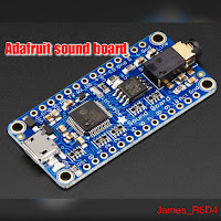
After posting up my 3D drawing for the new Adafruit sound board enclosure, I had questions so.... I found my old sound board, and was able to simply extend the design to a length suitable for it. I needed to add in a recess opening for the phono jack socket.
I've uploaded the stl file to my Thingiverse page, but as I'm not able to print off and test, as usual, due to working from home in this COVID-19 situation, the file is deemed a Work In Progress. If you do download to print it and find any issues, please let me know so I can update the file to better fit.
The above pictures show the designed enclosure, the sound board its designed to be used with and the final picture is my original sound board that broke, due to the plug bending and braking the socket off the board.

Extra Projects & Event Page's
- Home
- Trading Card Dispenser (version 2) - TCD [2020/2022]
- R5-D4 - Trading Cards
- R5-D4 - silver neck details
- R4-D4 - Dome [wood build]
- R0-D4 Dome [wood build]
- 3D Printing - Star Wars stuff
- *** Star Wars Shoes ***
- GOUD-4 Messenger Droid - Solo ASWS
- Event's 2018
- Event's 2017
- Event 2016 - "Celebration Europe"
- Event's 2015
- Event 2014 - Chippenham Sci-Fi
- R5-D4 - events page - The beginning (2013)
- ** R5-D4 patch **
- R5-D4 Photos
- Han Solo - costume for my Son
- Droid Caller - Han Solo style
- Boba Fett - costume build for my Son
- Scanning Crew Container - Transmitter Storage Box
- Stormtrooper - me
- ROGUE ONE - trading card storage box
- Rogue One
March 29, 2020
Sounds for droids 2020 - upgrade 1.2
Another step closer to upgrading R5's sound system arrived in the post this week.
My new Adafruit Sound Board. This is the 16MB version.
I got it from Pimoroni, here in the UK, total inc postage was £21.89.
Link to the product on the Adafruit website.
Link to Pimoroni website.
Next up was to solder in the contact pins
I only fitted pins i’ll be needing
and
then design up another 3D housing to print out at a later date lol.
This was version 1, I’ve since redesigned it to version 2.
Checkout my prev posts..
Sounds for droids 2020 - upgrade 1.1
And
Sounds for droids 2020 - upgrade 1.0
March 26, 2020
Utility arm servo linkages & bracket design - more work
I'm a bit stuck at the moment, with COVID doing the rounds, I'm now at home. All good, except the 3D printer is in work.
So am drawing up new versions a bit blind really. I extended the part of the bracket which has the two location holes in. Then looking at the position of the part that would connect to the servo linkage, I decided to re-position it and blend it onto the extended part.
So am drawing up new versions a bit blind really. I extended the part of the bracket which has the two location holes in. Then looking at the position of the part that would connect to the servo linkage, I decided to re-position it and blend it onto the extended part.
Utility arm action 2019/2020
(3.4.19)
This post is over a year old now, thought I’d posted it. Is quite a good way of introducing the upgrade as part of the reactivation of them.
—-
R5's utility arm(s) have been out of action for a few years now. They were deactivated for events after a servo was damaged & the utility arm pivot point bracket got broken.
I upgraded the pivot point into a more solid screwed together component.
The brackets needed to be opened up a bit more to allow free movement. With servo issues as well at the time and an event coming up, I decided to lock the arms safely in place.
UPDATE
I opened up the bracket holes and lightly sanded the arms pins that fit into them. They are now a lot easier to move.
This post is over a year old now, thought I’d posted it. Is quite a good way of introducing the upgrade as part of the reactivation of them.
—-
R5's utility arm(s) have been out of action for a few years now. They were deactivated for events after a servo was damaged & the utility arm pivot point bracket got broken.
original pivot point brackets
The brackets needed to be opened up a bit more to allow free movement. With servo issues as well at the time and an event coming up, I decided to lock the arms safely in place.
UPDATE
I opened up the bracket holes and lightly sanded the arms pins that fit into them. They are now a lot easier to move.
March 19, 2020
Utility arm servo linkages & bracket design
I wanted a way to better connect the utility arm servo linkage to the arms.
So after looking at how other’s had done this, I started looking at how I could design something up for my wood arms. AutoCAD inventor fired up, I started drawing up a bracket, that I can somehow fit/fix to the arm.
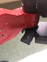
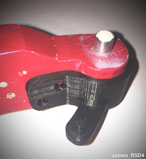
This is first design, but only had time to print one idea off. Got home and after test fitting, above pictures, I realised that the better fit would be flipped upside down, so that the arm part of the bracket face the other way. This would then clear the arms angle edge.
So a new design on Monday will be drawn up, also with some other ideas as well.
Version 2 print needed some more alterations.
Version 3 print needed some additional redesigning to include more support & possible fixing points.
Next up was looking at how to protect the servos from being over stretched. R2 builders who have opening pie panels on their domes and doors on their bodies, use this idea of spring loading the link rods. This gives some play as the springs take the additional strain of the panels being manually opened at events & damaging the servos.
Here the linkage protection is being tested on the first utility arm bracket.
This test was helpful in that it should the idea was on the right track...
More updates soon.
So after looking at how other’s had done this, I started looking at how I could design something up for my wood arms. AutoCAD inventor fired up, I started drawing up a bracket, that I can somehow fit/fix to the arm.
This is first design, but only had time to print one idea off. Got home and after test fitting, above pictures, I realised that the better fit would be flipped upside down, so that the arm part of the bracket face the other way. This would then clear the arms angle edge.
So a new design on Monday will be drawn up, also with some other ideas as well.
Version 2 print needed some more alterations.
Version 3 print needed some additional redesigning to include more support & possible fixing points.
Next up was looking at how to protect the servos from being over stretched. R2 builders who have opening pie panels on their domes and doors on their bodies, use this idea of spring loading the link rods. This gives some play as the springs take the additional strain of the panels being manually opened at events & damaging the servos.
Here the linkage protection is being tested on the first utility arm bracket.
More updates soon.
March 12, 2020
Littlebits - Star Wars Droid Inventor Kit - pt 10 (2020)
I've now uploaded the stl files to my Thingiverse page. As well as the standard 'open' pie hole lid, I've also uploaded the 'bad motivator' lid version.
Littlebits - Star Wars Droid Inventor Kit - pt 9 (2019)
22.10.19
Lid update.....R5 now has a 'Bad Motivator':
Printed off the updated R5 lid, which now has the correct orientation 'antenna' and also the 'bad motivator'.
The antenna's front circle needed to be facing the front in relation to the pie panel opening and the bad motivator positions.
I've uploaded a short video onto my You Tube account, it can also be found on my Instagram page.
UPDATE: 12,3,2020
The files have now been uploaded to Thingiverse
R5-2JE astromech - toy review by 'Galactic Hunter'
Galactic Hunter have been reviewing The Rise of Skywalker 'Factory Droids' set released by Disney for the film.
They have already reviewed D0, R2-SHP & R6-LE5....
Click link below:
Always good to see some love for an R5 😊
March 11, 2020
Syren 10 motor controller 3D printed housing
With all the alterations and upgrades going on in R5, I wanted a housing for the Syren 10 dome motor controller board. Just to add some protection to it.
I measured it & drew up a housing in AutoCAD Inventor (works program).
I wanted it to be a snug fit, but also allow access to the terminals, dip switches and also be able to see the LED indicators.
My first design, was good, but needed to re-position the openings a bit. The dip switch & LED openings needed adjusting.
The second print (picture below), I'd also increased the inside height a bit to allow the board to slid inside the housing easier.
Below is version 2 printed, as seen in previous picture.
Version three, had some more minor updates to the opening ends and this will be the version I put up on Thingiverse soon.
I measured it & drew up a housing in AutoCAD Inventor (works program).
I wanted it to be a snug fit, but also allow access to the terminals, dip switches and also be able to see the LED indicators.
My first design, was good, but needed to re-position the openings a bit. The dip switch & LED openings needed adjusting.
 |
| First housing design - Syren 10 speed controller |
 |
| Second housing design - Syren 10 speed controller |
~~~~
Version three, had some more minor updates to the opening ends and this will be the version I put up on Thingiverse soon.
March 06, 2020
Transmitter Ex7 switch upgrade - rotary to switch, part 2
Finished putting a groove in the new switch locking ‘cap’.
I used a grooving tip tool to scrape/shape the slot.
Got home and the posty had delivered the pack of resisters. So test soldered up the resistors & wires to the two switches and tested them with batteries in the transmitter. And the switch works, via the transmitters screen, still need to actually test via the reciever.
The above picture shows the resistors and wires soldered up to test it worked. Exposed wires will be insulated once completed.
My 'cap' fitted to the switch CH7 in picture above.
March 04, 2020
Transmitter Ex7 switch upgrade - rotary to switch, part 1
Most RC controllers have that one (or more) rotary dial ‘switch’ which for droid controlling, isn’t needed as such, so is just a waste of a switch. Yellow circled in next picture.
Searching up online and YouTube came up with ‘how to’ swap a dial switch for an actual on-off-on switch. Had already bought a switch ages ago, so next was to order a pair of resisters which replicate the potentiometer in the dial switch.
Whilst waiting for the resisters, I decided that rather than buy a pack of switch ‘caps’ or lock nuts, that holds the switch in place, I’d machine one up myself.
So lunchtime in work I found & machined up a piece of aluminium bar to almost the exact dimensions lol.
Just needs a slot added. Original is on the right.
March 03, 2020
Weekend work on R5 - TCD ,‘Trading Card Dispenser’ control box fitment
Last week I drew up a curved back, bracket to mount the trading card dispenser control box onto. I wanted its position to be closer to the TCD, ‘Trading Card Dispenser’, itself. The power distribution terminal blocks position had to be moved as the leads had already been connected. Still, it’s better as the 12 volt cables don’t have to reach as far round to the distribution block.
The main 12 volt cables still need to be connected up to the distribution block. The other pair of cables seen are to the dome motor, but require the speed controller to be fitted inline.
Subscribe to:
Posts (Atom)


