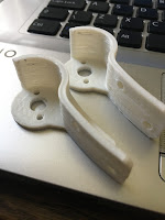
Without a 3D printer, I'm a bit stuck..... but as the circle of help goes around, I was offered printing from a fellow builder Chris. He sent me two brackets for me to test out, thanks mate.
The principle looks and fits well, but still needs some more fine tuning. So back onto the CAD and started measuring up and creating a new bracket. You might ask 'why not just use the dimensions from the plans?' .....because the Utility arms I made myself and although to the plans, are not 100% spot on. Hence having to work all this out on the go.
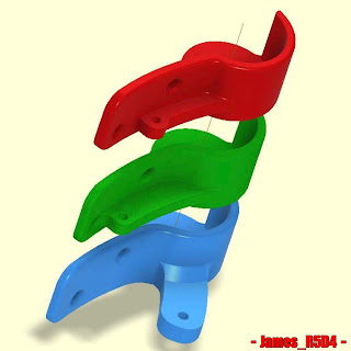
So here's the next version. I altered the radius angle from the contact point it has to better fit the inner curved face of the arm. Below are the 3 versions, the red version is the new revised one, green matches the ones supplied by Chris & the blue, the original version.
Here is the side view of the above brackets.
As you can see in the first picture, the red curved section, protrudes out further than the green. After being able to measure the difference, I was able to reposition it (hopefully) to be a better fit to the inner curved surface. It also doesn't have the angle joining it to the circular base section, seen in green. This got in the way of the arm angle so needed to be removed.
I have already been designing up other versions.
So more updates soon.

Extra Projects & Event Page's
- Home
- Trading Card Dispenser (version 2) - TCD [2020/2022]
- R5-D4 - Trading Cards
- R5-D4 - silver neck details
- R4-D4 - Dome [wood build]
- R0-D4 Dome [wood build]
- 3D Printing - Star Wars stuff
- *** Star Wars Shoes ***
- GOUD-4 Messenger Droid - Solo ASWS
- Event's 2018
- Event's 2017
- Event 2016 - "Celebration Europe"
- Event's 2015
- Event 2014 - Chippenham Sci-Fi
- R5-D4 - events page - The beginning (2013)
- ** R5-D4 patch **
- R5-D4 Photos
- Han Solo - costume for my Son
- Droid Caller - Han Solo style
- Boba Fett - costume build for my Son
- Scanning Crew Container - Transmitter Storage Box
- Stormtrooper - me
- ROGUE ONE - trading card storage box
- Rogue One
April 29, 2020
April 28, 2020
Sounds for droids 2020 - upgrade 1.3
Saturday I got round to playing with the sound board & set everything up to test out the new amp.
Rewind a week to the issues I had trying to upload the sounds to the board. I had just grabbed a usb cable I thought I had used before to connect the board to the laptop, but it wouldn’t connect???
After numerous attempts and system checks, I realised the cable was a power one not a power/signal one. Swapped cables and instantly problems solved lol.
After testing the sounds using my phone, i needed to actually test with the sound board. So after some wire soldering/connections, the board, amp, speakers where connected. I had ordered a potentiometer as a volume control, but it still hasn’t come, so I dug out a broken large servo and used the pot out of it. Quick YouTube/internet search, and it was soldered up according.
This might look like a mess lol, but it was only for the purpose of taking the pic.
I opened up the ground loop unit to be able to connect up the speaker wires.
The amp uses 12 Volts, but the sound board runs 3-5 Volts, so has a mini voltage regulator [just seen in picture above it],
The sound output was great! And even more so, when I adjusted the 'volume' via the potentiometer, so much so that the wife told me to turn it down! :D
This new amp was originally going to be used as a separate sound unit for in R5's dome, but I think I might keep it for his main sound setup and get another [possibly] for the bad motivator dome setup.
Here's a size comparison between the two amps:
Rewind a week to the issues I had trying to upload the sounds to the board. I had just grabbed a usb cable I thought I had used before to connect the board to the laptop, but it wouldn’t connect???
After numerous attempts and system checks, I realised the cable was a power one not a power/signal one. Swapped cables and instantly problems solved lol.
After testing the sounds using my phone, i needed to actually test with the sound board. So after some wire soldering/connections, the board, amp, speakers where connected. I had ordered a potentiometer as a volume control, but it still hasn’t come, so I dug out a broken large servo and used the pot out of it. Quick YouTube/internet search, and it was soldered up according.
This might look like a mess lol, but it was only for the purpose of taking the pic.
I opened up the ground loop unit to be able to connect up the speaker wires.
The amp uses 12 Volts, but the sound board runs 3-5 Volts, so has a mini voltage regulator [just seen in picture above it],
The sound output was great! And even more so, when I adjusted the 'volume' via the potentiometer, so much so that the wife told me to turn it down! :D
Here's a short video clip of the sound test, via my You Tube channel.
This new amp was originally going to be used as a separate sound unit for in R5's dome, but I think I might keep it for his main sound setup and get another [possibly] for the bad motivator dome setup.
Here's a size comparison between the two amps:
New amp on the left [small], original amp on the right [large].
The new amp cost about £5 inc P&P, compared to the SURE amp, which cost about £20+
Tuesday 28th and the potentiometer arrived in the post...
Tuesday 28th and the potentiometer arrived in the post...
April 20, 2020
Thingiverse Page - James_R5-D4 = Free downloads
Not done much on R5 these last few days. Have been answering questions about my Adafruit enclosures via my Instagram and Thingiverse pages.
So whilst I was on my Thingiverse page, I thought I'd checkout the views and downloads counts lol.
First up, top 7 Things viewed over the last year:
No.1 top spot, is my Trading card dispenser, lol this is like Top of the Pops 😂.
Next up, top 7 Things downloaded over the last year:
The Fake electronics board parts are what I created to be used for R4-D4's electronic panel on his dome [check out the page at top for the build].
Next up is my Trading Card Dispenser, this one is also No1 in my viewed 'Things'.
In third place are my Frankenstein neck bolts 😄. These I literally drew up and managed to get printed in an afternoon for work college who mentioned he was doing fancy dress the weekend lol.
April 14, 2020
Electrical System Update 2020 - 1.3 cable tidy
As I mentioned in my last post, I used yellow cable for the positive 12 volt side of R5’s electrical system. Connectors were soldered and heat shrink applied. Label's to identify were also added, before the expanding cable sleeve was applied to keep everything tidy.
Heat shrink was applied to the ends and I also added cable ties.
It's all now looking really neat!
Heat shrink was applied to the ends and I also added cable ties.
Terminal block to distribute 12 volt power.
Switch to control power to the feet motors,
having heat shrink applied over it’s terminals.
The switches in place with heat shrink applied.
Cables with sleeving and labels identifying 24 volt power system.
And a pic of the (almost) finished wiring setup.
It's all now looking really neat!
April 08, 2020
COVID-19 isolation at home - 3D design work
My work allows me to work from home, unfortunately the 3D printer is in work, so not able to print anything 😢 ......well.....it is their's 😆 lol
So I have been able to work on R5 and some other mini projects requested by friends.
Adafruit sound board
Re-re-soldered the contact pins on the adafruit sound board, changed them back to right angle ones. Easier for the leads to protrude out the side, rather than straight up for connections to the relay switch, for wherever it gets mounted.
Protection case for sound board
So because of the above, the 3D model had to be modified again to match.I added recesses in the base to allow the underside of the pins to sit in so the board sits flat.
3D models
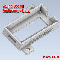
Been working on other 3D models for myself and friends. After a comment on my Instagram about the above sound board holder, I drew up one for the longer version, which has a headphone jack socket on it.
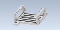
Next up was a holder for Paul's ESC unit. I had one of these he had lent me ages ago to try out in another project. So I was able to draw up a holder for him to test print one.
Th inside area was a bit too snug, so version 2 was a slight redesign and the addition of a rear bracket, tho this wasn't needed as the fit was just right.
And Paul was kind enough to send me some pictures of the unit fitted.
Recess' to allow the holder to fit over the top but not interfere with the cables.
Another club member wanted me to design up a mini slip-ring holder, for his holoprojector's.
This is still a work in progress.....
R5's cable management
R5 runs Red & Black power cable, as must builders probably do. His main power is 24 volts.
A while back (years) I bought some Yellow cable to match up with something....oooh yes, the 24 to 12 volt regulator. It has red/black wires in and yellow/black output wires for identification.
So rather than waste it, I decided that it would actually be a good thing to use for the 12 volt side of things. They're also now tagged with labels & clear heat shrink to aid identification.
R5's sounds
Got round to organising sounds, renaming them etc all ready to transfer onto the sound board. Then remembered that I couldn't connect the USB board as the files are virtual, as I'm remote desktop'ing to my works PC......aaaaaaahhhhh 😒
And for some reason, the USB sockets on this laptop are not recognising the drive, so will have to use another laptop.
So I have been able to work on R5 and some other mini projects requested by friends.
Adafruit sound board
Re-re-soldered the contact pins on the adafruit sound board, changed them back to right angle ones. Easier for the leads to protrude out the side, rather than straight up for connections to the relay switch, for wherever it gets mounted.
Protection case for sound board
So because of the above, the 3D model had to be modified again to match.I added recesses in the base to allow the underside of the pins to sit in so the board sits flat.
 |
| since been modified.....again. |
Been working on other 3D models for myself and friends. After a comment on my Instagram about the above sound board holder, I drew up one for the longer version, which has a headphone jack socket on it.
Next up was a holder for Paul's ESC unit. I had one of these he had lent me ages ago to try out in another project. So I was able to draw up a holder for him to test print one.
Th inside area was a bit too snug, so version 2 was a slight redesign and the addition of a rear bracket, tho this wasn't needed as the fit was just right.
And Paul was kind enough to send me some pictures of the unit fitted.
Recess' to allow the holder to fit over the top but not interfere with the cables.
Another club member wanted me to design up a mini slip-ring holder, for his holoprojector's.
This is still a work in progress.....
R5's cable management
R5 runs Red & Black power cable, as must builders probably do. His main power is 24 volts.
A while back (years) I bought some Yellow cable to match up with something....oooh yes, the 24 to 12 volt regulator. It has red/black wires in and yellow/black output wires for identification.
So rather than waste it, I decided that it would actually be a good thing to use for the 12 volt side of things. They're also now tagged with labels & clear heat shrink to aid identification.
R5's sounds
Got round to organising sounds, renaming them etc all ready to transfer onto the sound board. Then remembered that I couldn't connect the USB board as the files are virtual, as I'm remote desktop'ing to my works PC......aaaaaaahhhhh 😒
And for some reason, the USB sockets on this laptop are not recognising the drive, so will have to use another laptop.
Subscribe to:
Posts (Atom)


